• Published on

    Smoke and Mirrors

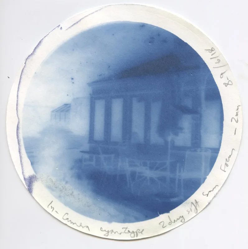
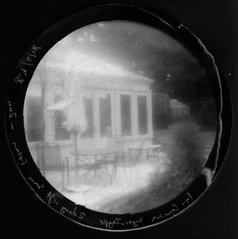
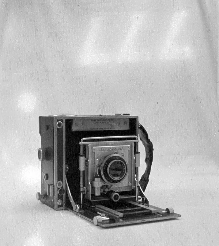
    I'm in the midst of preparing a talk on cameras which take photographs through mirrors. I don't mean mirrors in viewfinders and rangefinders, to qualify they must take the actual picture through one or more reflections. So this includes such things as stereo accessories which fit on the front of an SLR lens, mirror lenses themselves (catadioptric lenses) and many others. One of them is the ever-amazing Polaroid SX-70. This does indeed use a mirror to reflect the final image that's recorded, but even more fun is the optics of the viewfinder, so I took a picture of that using a semi-dismantled scrap SX-70, a laser pointer and a judicious touch of artificial smoke.
    Picture
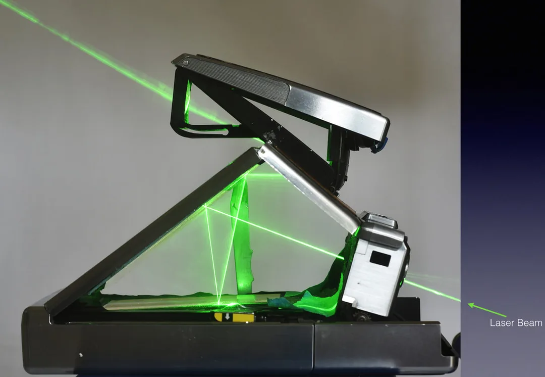
    The beam enters lower right, passes through the main lens, reflects in a plane mirror down to a fresnel mirror (with split-image rangefinder feature) which is on the upper surface of a movable flap, presently covering the filmpack. From there it is reflected back to the upper mirror again, and across to a concave (magnifying) mirror in the viewfinder housing. From there it passes through the viewfinder lens and on to the eyepoint. When the shutter release is pressed, the flap carrying the fresnel mirror swings up to cover the sloping plane mirror. There is another plane mirror on the underside of the flap, so we still have a mirror under the large sloping surface of the camera. The light coming in from the lens is thus reflected downwards to the now-uncovered film surface. And still in focus, because although the mirror is now a few millimetres lower, because of the thickness of the flap, the receiving surface is also a few millimetres lower - presumably all calculated to be an equal distance!
    Although I have seen diagrams of this before, I have never seen it in live action like this, so I thought it should be shared.
  • Published on

    Mercurial Batteries on a tight Budget

    Picture
    As we all know, the traditional mercury battery has long been discontinued, and substitutes have to be found to power many cameras and exposure meters of the 1960s. The commonest battery of the time was the PX625, aka PX13 or LR9. A large number of alternatives are on offer, many of them rather expensive, so I thought I would have a go at a bare-bones solution. I have relied heavily on the published work of Frans de Gruijter who has analysed the problem in depth, and offers a neat kit to convert the shell of an old 625-size battery to carry a silver oxide cell to produce the necessary 1.35V.
    ​The nub of the issue is that to keep the circuit cheap, most designers at the time relied on the fact that a mercury cell gives a nearly constant voltage all its life before dying suddenly, so the meter could rely on the battery to give a fixed known output. The electronics could then consist of nothing but battery, LDR (light dependent resistor - the light-sensitive CdS or CdSe cell), meter and one resistor, all wired in series. It’s that simple!
    So what other cells give the constant voltage we need and are still available? Several, is the answer, but easily the best for us is a silver oxide cell which gives a nearly constant 1.55V. You can put one of these directly in a meter but it is likely to read too high by several stops, and be non-linear. We need to reduce the battery voltage by 0.2V, and the way to do that is a suitable diode (a Schottky diode) which creates a voltage drop of 0.2V, that itself is also constant; a resistor would give a voltage drop proportional to the current flowing, which would not do at all. The diode is wired in series with the battery.
    This is the conclusion reached by Frans de Gruijter, and is the basis of his conversion kit – which I have tried and can recommend. But maybe we can slim it down even more? Here goes.
    ​The slimline adaptor is a paper disc with a conducting layer each side, with the diode soldered to the edge of each layer. This slips under the battery, with the diode near the edge of the compartment, where the shape of the battery leaves a little space. The pad itself is less than 0.5mm thick and should not cause any clearance problems in the instrument. If your device needs two batteries, you also need two adaptors.
    Materials needed:
    • 300gsm red card – 60p for an A4 sheet at our local art shop.
    • Self-adhesive copper foil. This is sold in garden centres to deter slugs. A roll 22-25mm wide and a couple of metres long costs about £4. The copper is very thin, and is supported on backing paper. Enough here for hundreds of adaptors, or use the rest for its intended purpose!
    • Schottky diode – Type BAT-46 is readily available and suitable. I bought a pack of 25 for £3.52 from eBay – 14p each.
    • Battery – silver oxide type 357 (aka SR44) – priced between 50p and £1.50 each depending on brand and source.
    • Electronic solder with incorporated flux.
    • An O-ring 11mm ID x 14mm OD, may be useful to keep the battery centred in the compartment, depending on the details of the design of the camera / meter. 
    Picture
    So someone wanting to make half a dozen adaptors to fit a few devices, could buy the necessary for £10-12 and still have spare materials for future use. The battery itself is by far the biggest expense, of course. When it needs to be replaced, the adaptor can be re-used. However, the adaptor is relatively fragile, being made of paper, thin foil, and a tiny glass-bodied diode. So it might have an accident; however, if you have bought materials in the quantities mentioned, you can make a replacement adaptor without battery for about 20p.
    Tools needed:
    Most of the job can be done with readily available hand tools – a craft knife and scissors are useful, tweezers, small snipe-nose pliers, and a fine-tipped soldering iron. The trickiest part is probably the punching out of neat discs of paper and backed copper foil, best done with wad punches. These can be bought individually, or as a set of punches with a common handle. You need two sizes – either 3/8” and 7/16” or 10mm and 11mm would do. Expect to spend around £20 if you need to buy these. I happen to have a small hand-press which does a good job of punching out these materials. But usually you would use a block of wood and a hammer, and you need to give the punch a surprisingly meaty thump even when just cutting paper.
    Construction sequence:
    Cut a piece of the red card to approximately the width of the foil tape, and stick down a length of the copper foil, to cover one side.
    Using the larger punch, punch out as many discs as you like. A piece of material 8”x1” should make 20-odd discs. Each disc should be completely covered with copper on one side, and bare card on the other.
    Using the smaller punch, punch out the same number of discs directly from the copper foil plus its backing paper. This should give you a set of discs with the copper on one side and still on backing paper.
    Using the tweezers, lift the copper from these smaller discs one by one, and stick them to the bare card side of the larger discs, trying to keep an even margin of red showing all the way round. I call this side of the card the positive side. You need to be sure not to get a short-circuit between the copper pads on the two sides of the card.
    Picture
    Now for each disc:
    With the soldering iron, make a little dot of solder just at the edge of the positive pad.
    Take a diode, and note the black ring round one end. Trim that lead to about 6mm long. Hold the lead with fine-pointed pliers, butted up to the diode, and bend it about 70°. The reason for the pliers is not to do the bend at the actual end of the diode body, which is fragile.
    Hold the diode by the other lead, so that it is positioned on the edge of the disc, over the red rim, roughly parallel to the edge, and with the end of the short lead over the little solder dot you made. Solder lead to dot (only a couple of seconds contact at most, so the diode doesn’t get overheated).
    Using the thin pliers as before to protect the diode body, bend the second lead up and around the edge of the disc, so it lies flat and in close contact with the edge of the negative pad. Trim off the excess lead and solder in place, rapidly as before.
    That’s it done.
    Picture
    Back row, negative side up - front row, positive side (red ring) up
    Is it working?
    If you have a digital multimeter you might want to check your work. As well as the meter you will need a resistor to allow a small current to flow during the test – the voltage drop created by the diode won’t appear without a little current. The value of the resistor is not critical, but something in the region of 10kΩ will be fine. Use some kind of clip or clothes-peg to clamp together the battery and the newly made disc, with the resistor to complete the circuit. The positive face of the pad should be in contact with the negative face of the battery. Now measure the voltage across the test resistor. Likely results:
    - About 1.3V – success!
    - About 1.5V, same as the battery on its own – a short-circuit between the two pads of the adaptor.
    - About 0v – damaged diode, or the wrong way round.
    Picture
    ​Installation and use:
    The battery compartment of your camera or meter will usually have a spring contact in the bottom (negative), space for one or two cells, and a screw-on metal cap (positive) which retains everything and completes the circuit. Drop an adaptor in first, make sure the red ring is visible – i.e. positive side up. It should cover the spring contact, but leave the diode near the edge so it doesn’t get crushed. Put an o-ring on the battery if it seems to help centre it, and drop the battery on top, positive side up. Screw on the cover.
    If your device needs more than one battery, it will need an adaptor for each. Electrically it doesn’t matter what order they all go in, but for physical fit I recommend alternating batteries with adaptors. Trying this with a Gossen Lunasix, that was easily the best way to go, and produced accurate readings.
    That should be it. Try the meter, comparing it with a known good one if possible. As the optical characteristics of meters vary, they may not agree exactly but should be close. Try both high and low light levels. When the battery needs replacing, look after the adaptor – it can be re-used indefinitely so long as it is not damaged.
    Picture
  • Published on

    Desert Island Photography - The 2018 campaign

    For the background to this story you will need to look back to my posts in July and October 2017. Not giving up despite the setbacks of last year, I can now report progress.

    The new camera needs at least to defeat the problems of 2017. One constraint remains – spinach is still the preferred light-sensitive material, and its sensitivity is very low. The f/2 lens is not really fast enough, but nothing faster is in sight, so we are committed to one exposure taking the whole summer. There is also no large budget for this experiment.
    After some thought, I worked out that my lens would fit neatly enough into one end of a 5-litre paint can. And paint cans are airtight. Online I was able to buy two new unused cans for under £10, which was the main expense; the rest of what I needed – wood, paint, glue, etc – all came from stock. A chunk of wood forms the chassis, and adds a little length so that the lens will focus on the lid of one of the cans, whilst the other can takes the role of the lens-hood. The lens is silicone-sealed to the wooden block, and the two cans, with holes cut in both their bases, are screwed to the wood. The rear can is the camera, and a plastic ring in which I embedded some magnets holds a coated paper disc to the inside of the lid.
    We have belt and braces to keep the paper dry and fungus-free – the sealed can, a bag of Molecular Sieve 3a (a desiccant) lying inside the camera, and a pinch of thymol fungicide mixed into the spinach juice coating the paper.

    However, before the 3-month trial using anthotype, it seemed prudent to run a 2-day exposure with cyanotype paper. I’d tried this in the first camera, and knew that would be the right exposure. Remember that the lens is a totally uncorrected single plano-convex lens intended as half of a condenser.
    Picture
    The in-camera cyanotype test negative, exposure 2 days
    Picture
    Scan from the cyanotype negative - flipped, inverted and converted to b/w
    The test was successful, so on to anthotype. The paper is smooth drawing paper, double-coated with spinach; the juice made with a hand-held blitzer and filtered off with a coffee filter, a pinch of thymol crystals added. No ethanol but a little water was added.
    ​The aim was to prevent mould by a combination of a sealed environment, thymol and desiccant. That was a complete success, and when removed after three months the paper was dry to the touch and free from mould or fungus - unlike in 2017. The camera was pointed at the same scene as the cyanotype exposure, so we are looking for the same image as that. You can distinguish the main structure of the building – it looks better if you stand back and try for an overall impression – but much lower contrast and nowhere near the amount of detail to be seen in the cyanotype. 
    Picture
    The 3-month exposure on spinach-coated paper
    Picture
    The same, flipped and converted to b/w
    So was this a successful experiment? I would say definitely yes! As far as I know this is the first published in-camera anthotype. I confidently expect there to be very few others, this is not likely to be a new trending practice in photography. With exposure times of three summer months barely adequate to produce an image, only a few subjects are even possible, and the prospects of a body of work are near zero. However, a result was achieved against significant odds.

    It is also worth noting that the test method, using cyanotype paper in-camera, is also hardly ever done but is a lot more promising as a practical technique. With exposures in single figures of days, you could certainly contemplate a series of images, of a rather magical nature.

    As for me, though, I shall declare success and move on.
  • Published on

    Aerographic and PC-TEA

    Continuing to use Kodak Aerographic 2645, as I have been doing some comparative testing of twin-lens reflexes that use 127 film (yes, I know, why would you?) In due course I hope to have a comparative report here so you can decide which to buy.
    Meanwhile a note on developing. As well as the late Patrick Gainer's ascorbate developer, I am trying his PC-TEA formula. You can read all about it here.
    P=phenidone, C=Vitamin C, TEA=triethanolamine. Thus PC-TEA.
    Now triethanolamine is an interesting liquid, because it is both an organic solvent and an alkali. That is to say, if you dissolve your developing agents (ascorbic acid=Vit-C and a pinch of Phenidone) in neat TEA (not tea!), they are not exposed to any water. The theory is that rather like rusting iron, for the developer to go off it needs to be in the presence of both air and water. So a stock solution of developing agents in TEA should have a very long shelf life. When you want to use it, 8ml of stock solution + 392ml of water makes 400ml of working developer, used 1-shot. The clever bit is that the TEA, having so far worked as the solvent, now becomes the alkali and activates the developers. The benefits are several - a very dilute working solution, so minimal environmental or health risks, long shelf life, cheap to make and use. And the actual performance is fine, with developing times similar to other brews.
    Vitamin C is safe to handle, TEA is a common ingredient of cosmetics (though it should not actually be drunk), and the phenidone content of the working solution is only 50 milligrams per litre.
    If there is a snag, it is that TEA is viscous at room temperature, so I find it best, when I make up a batch, to dose it into little screw-top tubes each containing 8ml (enough for 1 tank of working developer). While it is still hot, once you have dissolved the developing agents, it is easy to measure it into the tubes with a 10ml syringe.
    ​Here is a picture taken on Aerographic 2645, developed in PC-TEA. Camera - Yashica 44LM
    Picture
    Update some months later:
    Storage life is looking good so far. The PC-TEA concentrate is pale straw colour when first made. After about 5 months, in little individual sealed glass tubes (10ml tubes containing 8ml of concentrate), the liquid has darkened to near-black, but still works as normal!
  • Published on

    Using Kodak Aerographic 2645 Film

    I am enjoying trying out an assortment of TLRs that make 4x4 images on 127 film. But I am not keen to pay about £12 per roll of film, especially as some of these first trials are more likely to produce lists of problems to fix, than artistic pictures.

    In the back of a cupboard I find several rolls of Kodak Aerographic film, 240mm wide and 20m long. Packed in an amazing cassette, like a 35mm cassette but huge. If cut down to 610mm long and 46mm wide, that is really a huge number of 127 films, just for the trouble of cutting it up and sticking to the backing paper of used rolls of 127, or even backing paper from 120 suitably cut down and marked with frame numbers by hand.
    Picture
    This is the film I am using - a sealed box just opened. Made in 1990 and used in 2018, and not kept refrigerated, so will it be OK? And how to use it? The web contains almost nothing about this particular Kodak film, though there is plenty on other varieties, most of which seem to have extended red and reduced blue sensitivity; a bit like having a yellow filter on the lens, permanently?

    ​After a preliminary trial of developing conditions, I fixed on 8 minutes at 20°C in Gainer's Ascorbate developer, something I have using a lot recently. Here is a result:
    Picture
    Exposed at 50ASA in this case. Exposing at 200ASA produced a less dense but quite usable negative, so this film has good latitude. Taken with a Koni-Omega Rapid using Aerographic film hand-cut down to 60mm wide and mounted on recycled 120 backing paper.

    ​How does it compare for resolution with other films? I have not done a comprehensive survey, but here is an example:
    Picture
    Kodak Aerographic - detail scan from the previous picture. Little grain, excellent definition!
    Picture
    HP5+ in Rodinal - admittedly not expected to be the sharpest of the bunch, but I happen to have the same scene taken a day earlier with the same camera. Same magnification. Big big grain.
    Conclusion so far - very promising, and the film is still excellent after 28 years of cupboard storage. I shall be taking some 127 pictures soon!
  • Published on

    Can I get a Replacement?

    Picture
    Picture
    Dawe Universal press camera taken with a Minolta Miniflex 4x4 TLR on Agfa Superpan Supreme.
    I bought an odd roll of 127 film for 50p from Doug Palmer's lovely shop in Bridport a few weeks ago. Needing to try out a new (old) camera, I unwrapped it and found myself with a roll of Agfa Superpan Supreme, no less, which from what I can gather would have been made during World War 2. I peeled off the tape and found this little notice, which clearly says that if I am not fully satisfied I can send the negatives to a New York address for a free replacement roll. I reckon that at the time of exposure it was about 75 years old, and had not been stored in a chiller.
    I loaded my camera - a Minolta Miniflex - exposed the film at a guessed 50ASA and developed it in Gainer's developer, which is basically vitamin C with some alkali and a tiny pinch of phenidone. Wonders will never cease, I got pictures of reasonable density and no fog! On closer inspection, though, there were two problems - the grain is very squidgy and what should be even tones are uneven, plus the frame markings on the backing paper have printed across into the emulsion and can be seen on each picture.
    ​Can I send it back?