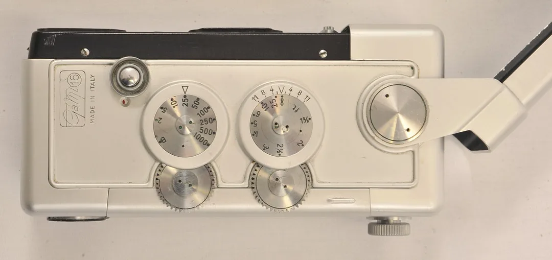
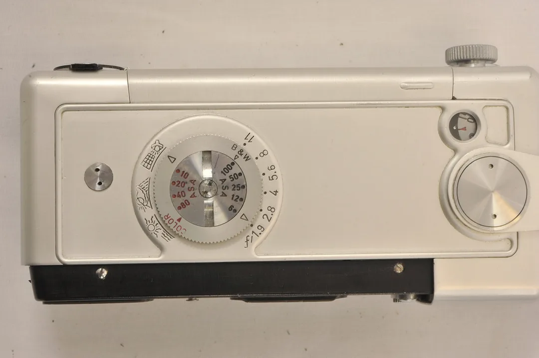
The Gami-16
Made in Italy by Officine Galileo around 1955. More information at www.gami16.it. There is a button for an English version.
Maybe the best of all the subminiature cameras of the 1950s. Here are some notes on a repair I had to do.
Warnings
The GaMi-16 is a difficult camera to work on, and should only be attempted by the experienced. If you get into difficulties I cannot help you.
This is not a general description of how to repair this camera. I merely record some experiences when I was unable to get detailed information on how to get into the camera, and had to fly by seat of pants. My camera had a specific fault which turned out to be a dislocated spring in the shutter release, and I only went as far as I needed to fix that, and then retreated. There are many other potential problems, which I did not need to solve. However, once you are inside, the actual engineering is of excellent quality and how to repair it should be obvious to an experienced camera restorer.
DANGER – the mainspring is strong and potentially dangerous, and needs to be run down completely before the main internal body is opened. However, the outer covers can be taken off without this hazard. The spring itself won’t fly out (it is in a barrel), but we don’t want wheels whizzing out of control.
Tools
Whilst normal tools will be used frequently, even to get as far as I did required me to make half a dozen special tools. They are not complicated, and a basic workshop will suffice, together with the usual box of scrap materials to make things from. I used a lathe to make one of the tools, but with care you could manage without.
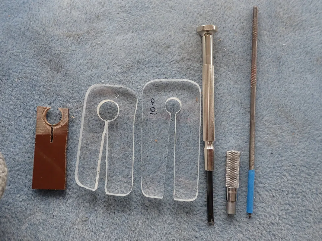
The two-pin screws are too small to be handled safely with an adjustable wrench. Make a fixed driver with two pins about 0.65mm diameter, exactly 3mm apart. The pins should be hard – I used piano wire, or broken drills would also do. The handle is mild steel, about 6mm diameter and knurled for grip.
Grip tools: I made small versions of the grips used to get recalcitrant filters off lenses. Take a piece of scrap sheet material (I used acrylic sheet; it should be hard, but softer than the metal being gripped), make a hole (using drill then reamer) accurately matching the OD of the part to be removed, and saw a slot up from the “handle” end to allow it to spring slightly. This gives a very strong grip, evenly distributed, and won’t mark the component. You need several sizes.
One screwdriver with a notch in the blade is needed for the aperture control.
Keeping notes
I recommend taking lots of photos of your own camera as you go. I found this very helpful later when putting it back together, and not just for writing this memo.
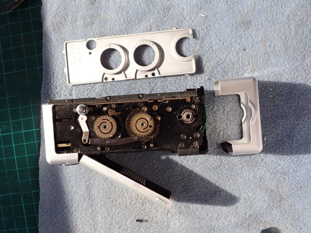
Front face
The black front cover with windows comes off easily using obvious screws. Four screws at the sides, and one tucked under the end. Interestingly, when you later take the bottom end cover off you will see what appears to be the only design “bodge” in the camera – this end screw fixes into an afterthought piece glued into the inside of the bottom end cover.
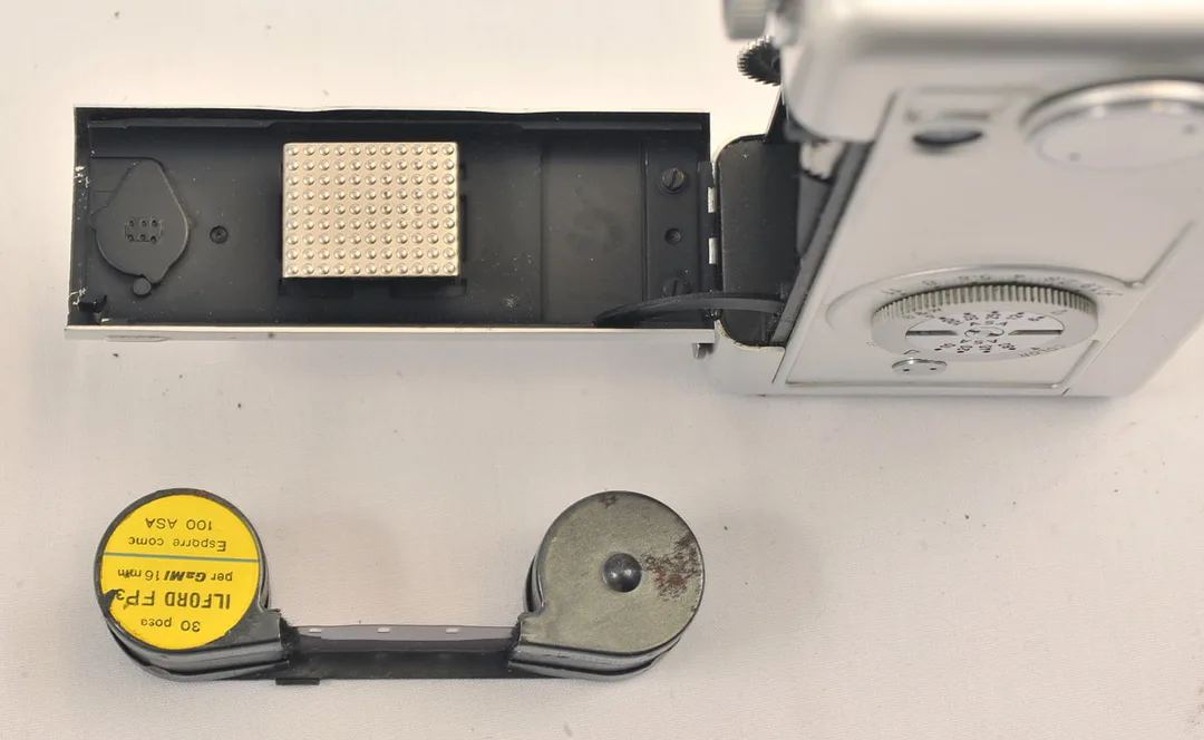
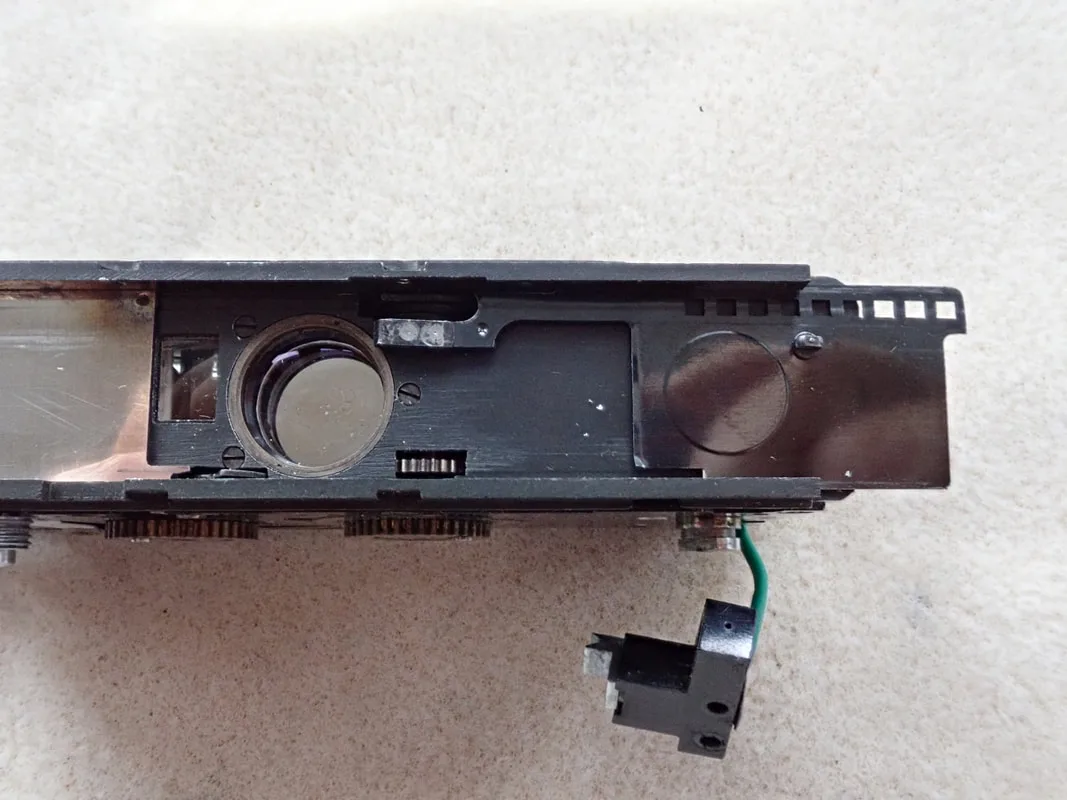
Removing this black cover gives access to the two sliding leaves of the shutter. For some repairs this may be enough, which would be a great boon as going much beyond here it gets more difficult.
Front cover / Winder
There are large-headed retaining screws each side, removed with the sort of adjustable wrench used for getting lens cells out – with pin ends fitted to the wrench. Just take these screws out, spring the sides of the cover out slightly, and take off the cover. Not dangerous.
The GaMi-16 is a difficult camera to work on, and should only be attempted by the experienced. If you get into difficulties I cannot help you.
This is not a general description of how to repair this camera. I merely record some experiences when I was unable to get detailed information on how to get into the camera, and had to fly by seat of pants. My camera had a specific fault which turned out to be a dislocated spring in the shutter release, and I only went as far as I needed to fix that, and then retreated. There are many other potential problems, which I did not need to solve. However, once you are inside, the actual engineering is of excellent quality and how to repair it should be obvious to an experienced camera restorer.
DANGER – the mainspring is strong and potentially dangerous, and needs to be run down completely before the main internal body is opened. However, the outer covers can be taken off without this hazard. The spring itself won’t fly out (it is in a barrel), but we don’t want wheels whizzing out of control.
Tools
Whilst normal tools will be used frequently, even to get as far as I did required me to make half a dozen special tools. They are not complicated, and a basic workshop will suffice, together with the usual box of scrap materials to make things from. I used a lathe to make one of the tools, but with care you could manage without.
The two-pin screws are too small to be handled safely with an adjustable wrench. Make a fixed driver with two pins about 0.65mm diameter, exactly 3mm apart. The pins should be hard – I used piano wire, or broken drills would also do. The handle is mild steel, about 6mm diameter and knurled for grip.
Grip tools: I made small versions of the grips used to get recalcitrant filters off lenses. Take a piece of scrap sheet material (I used acrylic sheet; it should be hard, but softer than the metal being gripped), make a hole (using drill then reamer) accurately matching the OD of the part to be removed, and saw a slot up from the “handle” end to allow it to spring slightly. This gives a very strong grip, evenly distributed, and won’t mark the component. You need several sizes.
One screwdriver with a notch in the blade is needed for the aperture control.
Keeping notes
I recommend taking lots of photos of your own camera as you go. I found this very helpful later when putting it back together, and not just for writing this memo.
Front face
The black front cover with windows comes off easily using obvious screws. Four screws at the sides, and one tucked under the end. Interestingly, when you later take the bottom end cover off you will see what appears to be the only design “bodge” in the camera – this end screw fixes into an afterthought piece glued into the inside of the bottom end cover.
Removing this black cover gives access to the two sliding leaves of the shutter. For some repairs this may be enough, which would be a great boon as going much beyond here it gets more difficult.
Front cover / Winder
There are large-headed retaining screws each side, removed with the sort of adjustable wrench used for getting lens cells out – with pin ends fitted to the wrench. Just take these screws out, spring the sides of the cover out slightly, and take off the cover. Not dangerous.
Body covering
The key to taking the body coverings off is removing the end caps, which retain the side plates with little overlaps. And the key to doing all this neatly is to make tools to grip the various components. Previous workers on my camera had not been careful enough, so there are some visible scratches – but at least I didn’t make it any worse.
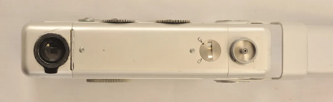
The main problem is the viewfinder window. It should really have a C-spanner made, which can only be somewhat less than 1mm thick at the point of engagement. Unlike the other components, there are severe constraints. The dioptre adjustment restricts access to the ring underneath which we are trying to undo, and the hinge for the back prevents us from making the normal gripping tool as above. I considered making a C-spanner, but first I tried grinding a small square-end tool that snugly fits the square notch in the ring – I repurposed a worn needle file. With care I was able to engage that and push it round, as fortunately the ring was not very tight. This is a dangerous solution which risks scratching the decorative surface, so is not recommended. However, once the ring is undone, the little optical assembly can be manoeuvred out quite easily.
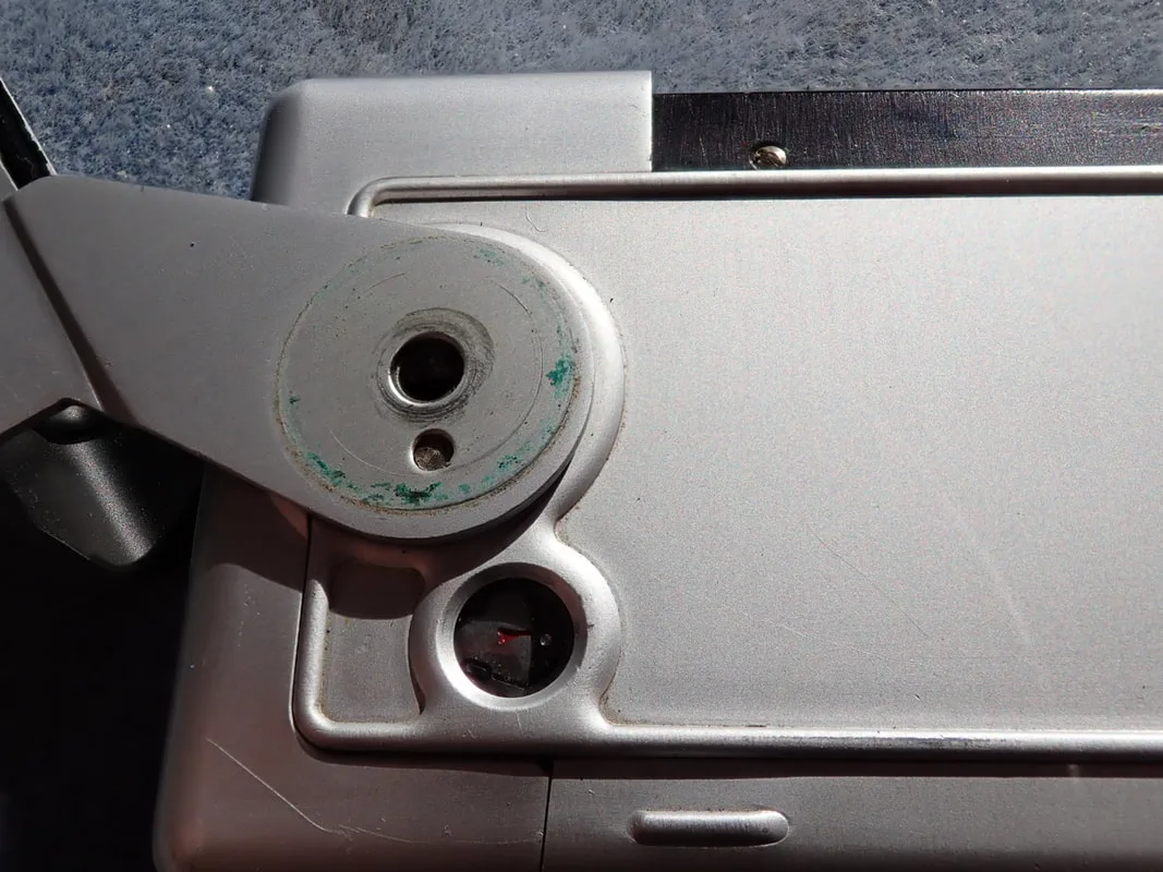
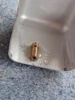
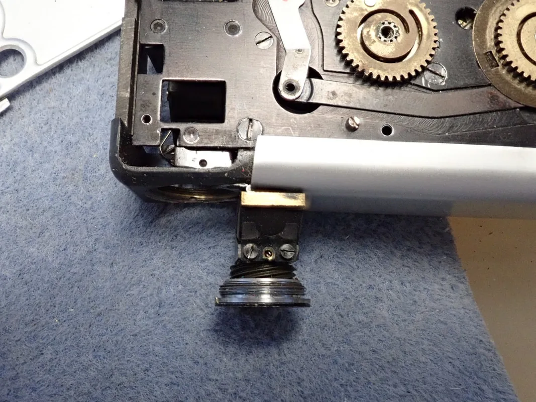
Remove the other visible components with grip tools. The tripod bush unscrews using one of these grips, but not before loosening a long diagonal grub screw under the edge of the front cover, which is there to ensure that the tripod bush doesn’t come adrift in use.
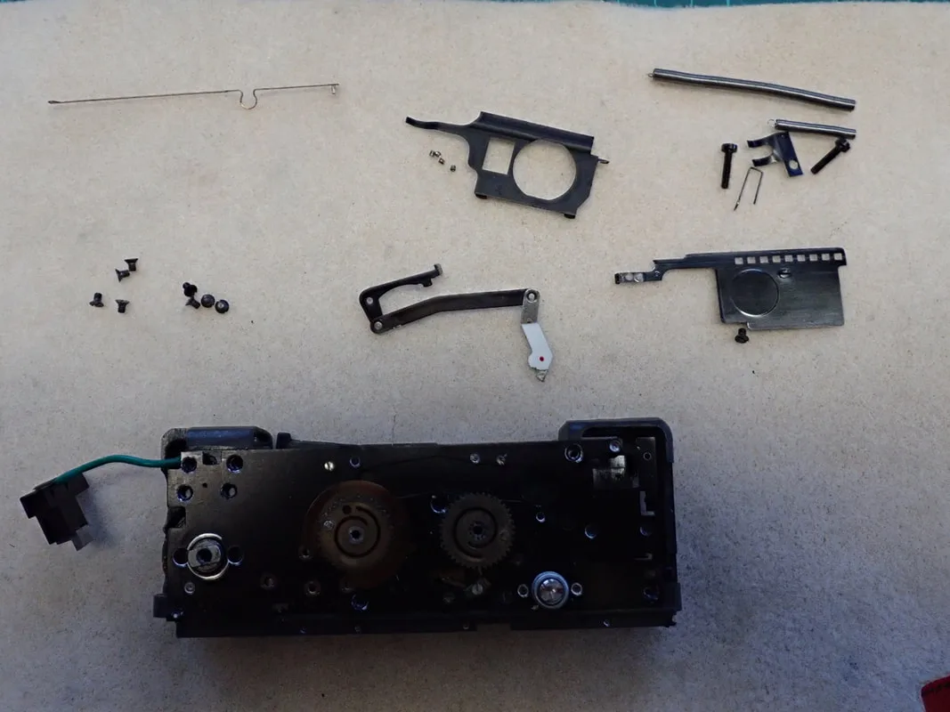
The end caps now come off, and after removing the controls (note positions!) and one more screw with your 3mm driver, the side plates are free. There is a loose ballbearing providing the click-stops for the aperture control – do not lose.
The key to taking the body coverings off is removing the end caps, which retain the side plates with little overlaps. And the key to doing all this neatly is to make tools to grip the various components. Previous workers on my camera had not been careful enough, so there are some visible scratches – but at least I didn’t make it any worse.
The main problem is the viewfinder window. It should really have a C-spanner made, which can only be somewhat less than 1mm thick at the point of engagement. Unlike the other components, there are severe constraints. The dioptre adjustment restricts access to the ring underneath which we are trying to undo, and the hinge for the back prevents us from making the normal gripping tool as above. I considered making a C-spanner, but first I tried grinding a small square-end tool that snugly fits the square notch in the ring – I repurposed a worn needle file. With care I was able to engage that and push it round, as fortunately the ring was not very tight. This is a dangerous solution which risks scratching the decorative surface, so is not recommended. However, once the ring is undone, the little optical assembly can be manoeuvred out quite easily.
Remove the other visible components with grip tools. The tripod bush unscrews using one of these grips, but not before loosening a long diagonal grub screw under the edge of the front cover, which is there to ensure that the tripod bush doesn’t come adrift in use.
The end caps now come off, and after removing the controls (note positions!) and one more screw with your 3mm driver, the side plates are free. There is a loose ballbearing providing the click-stops for the aperture control – do not lose.
The internal body is now a self-contained mechanism in which most of the functions, particularly shutter operations, are usable just as in the fully assembled camera. You can wind up the spring if necessary; either use the front cover, turned over (but don’t scratch it) – or make a separate tool.
Shutter
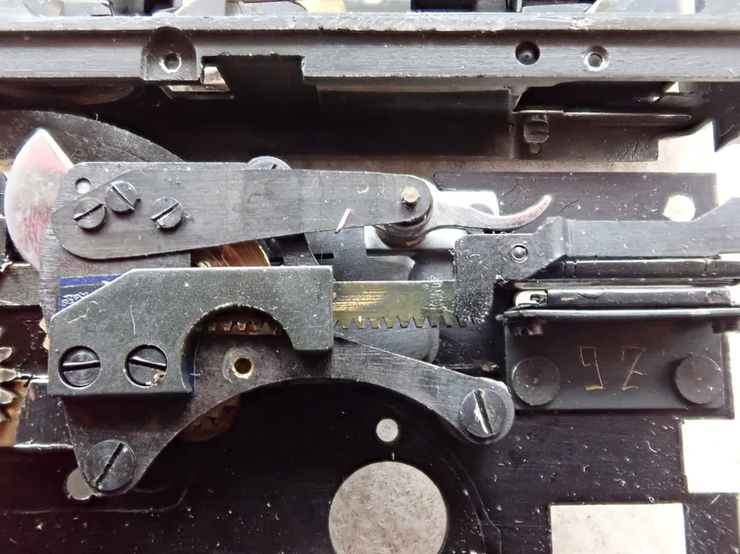
In my case after careful study of the shutter it was clear that a little plated hook that catches and releases the bright shutter leaf should spring upwards, and didn’t. Either the spring was broken or it was disengaged.
The black inner shutter cover comes off without drama (4 little screws). The two long springs that pull the shutter leaves are easily removed (1 screw, pull the pin), and the sync connection can be unscrewed and left connected but dangling. This allows the black shutter leaf to slide out. The bright shutter leaf does not come out readily, and may not need to.
Shutter
In my case after careful study of the shutter it was clear that a little plated hook that catches and releases the bright shutter leaf should spring upwards, and didn’t. Either the spring was broken or it was disengaged.
The black inner shutter cover comes off without drama (4 little screws). The two long springs that pull the shutter leaves are easily removed (1 screw, pull the pin), and the sync connection can be unscrewed and left connected but dangling. This allows the black shutter leaf to slide out. The bright shutter leaf does not come out readily, and may not need to.
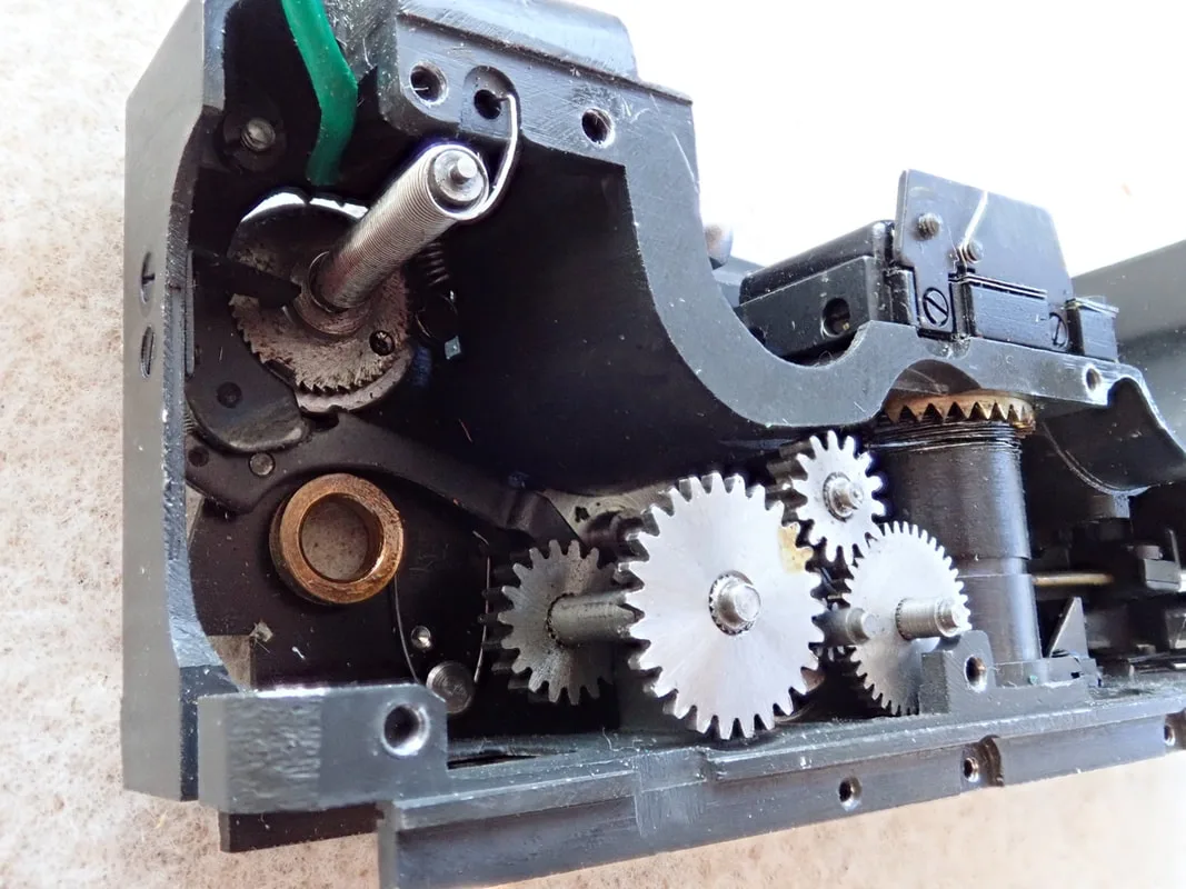
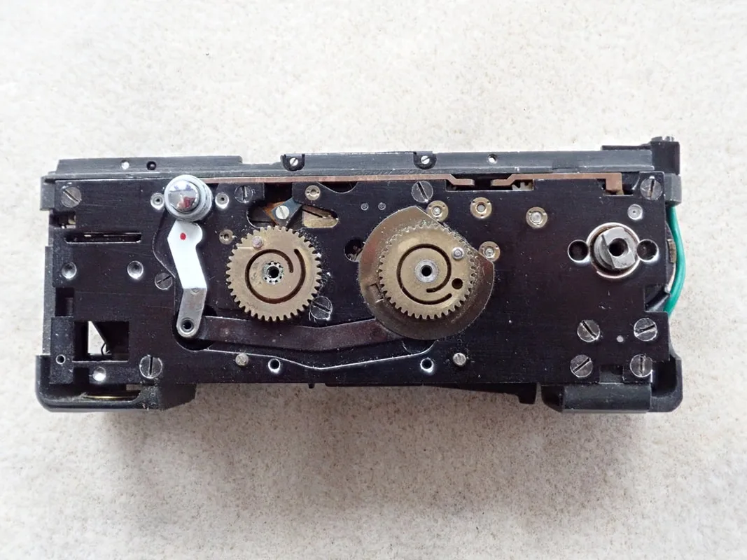
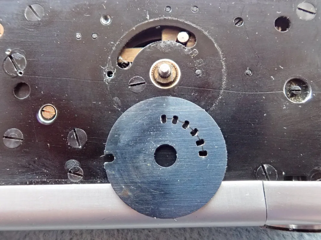
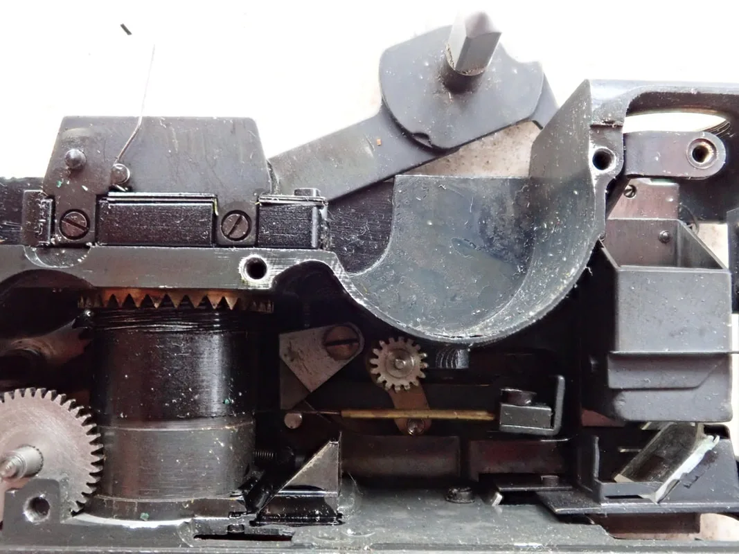
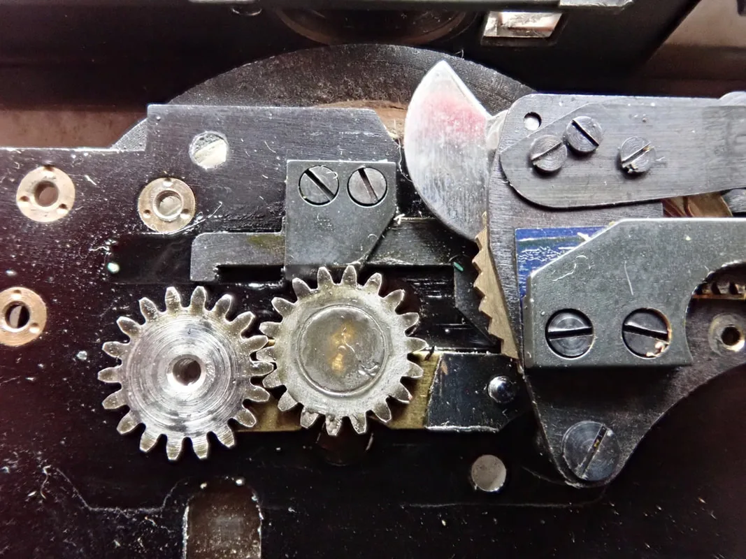
Now make sure the mainspring is fully unwound! The side plate on the side with the shutter speed control needs to come off – remove the 9 large-headed screws and lift the plate upwards looking out for two shutter parts that protrude towards the shutter blades – the little plated hook, and the restrainer that creates the slower speeds. The plate comes off complete with the shutter mechanism, which can receive normal service attention – clean and lubricate.
In my case I could immediately see the spring for the little hook, which had got displaced and was easily hooked back.
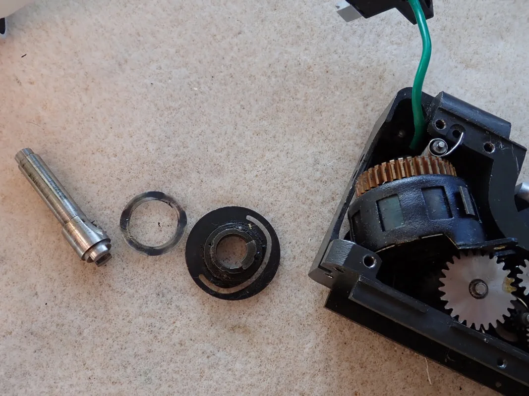
Mainspring
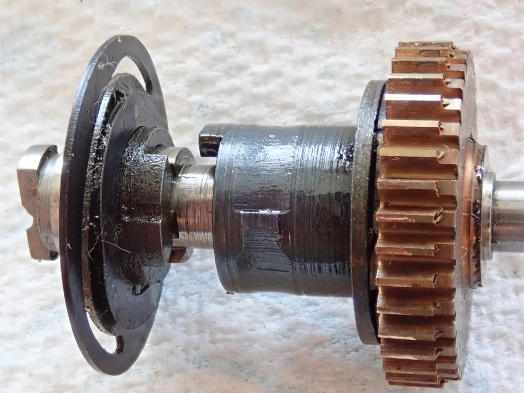
When I was working on the shutter, the central shaft of the mainspring came disconnected from the spring itself. This is irritating but not especially hard to fix.
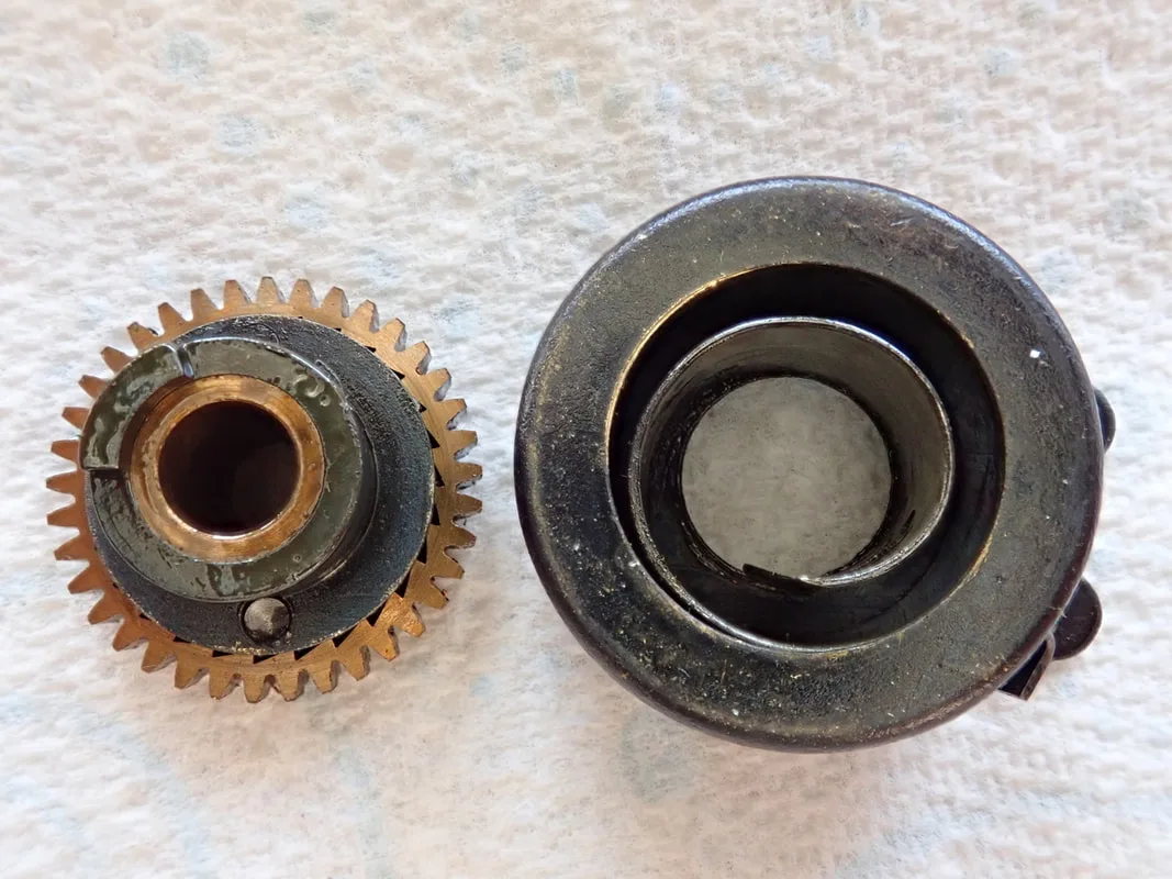
With the side plate off to work on the shutter, and the central shaft of the spring drive pulled out (as it had disconnected itself) the spring barrel can be wriggled out and back in; it is a bit tight but it does go.
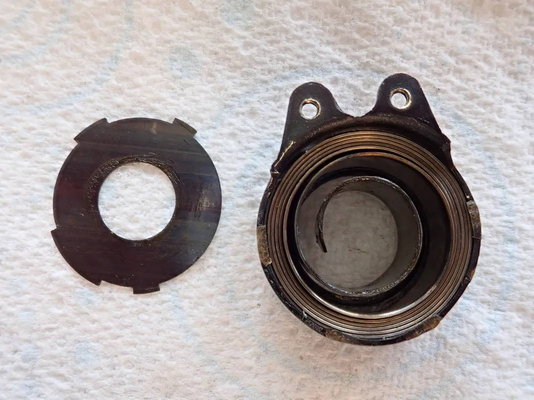
The design is just like a clock with the spring coiled in a barrel. Servicing is just like a clock too, so if you should have a broken mainspring look elsewhere online for instructions on clock repair, it is just the same and should be straightforward. In this case I fixed it by taking off the endcap off the barrel, which is a snap fit, to see the inner coiled end of the spring with a hole that engages with a tooth formed on the shaft. I bent the spring end a bit tighter with pliers, so the first half-turn now gently grips the shaft instead of being a little loose. The tooth will now always catch in the hole.
Reassembly
Reassembly is mostly a straightforward reversal of the dismantling process, except at the start:
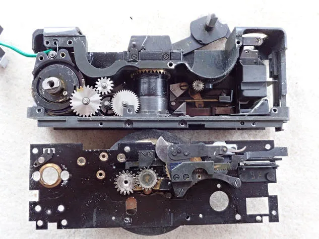
First to go back, and the trickiest, is the side plate of the main structure, which carries the shutter mechanism. This is manoeuvred back into place vertically, but with a lot of care to get everything back where it should be. The two moving pieces that had to be pushed into position when dismantling must be managed again, and now there are also five shaft ends to be settled back in their bearings. Once that’s done, and the shutter is still firing as it should, then the outer case can go back.
A good order of reassembly is:
- Top end cap, with the viewfinder part first and then the release button for the front latch.
- Left side plate, with the aperture control including its clickstop. Also include washers for that end of the wind mechanism.
- Right side plate, retained for now only with the shutter release collar.
- Bottom end cap, including locking the rotation of the tripod socket.
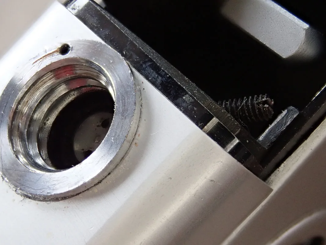
Left - The black diagonal screw on the right locks the tripod bush in place.
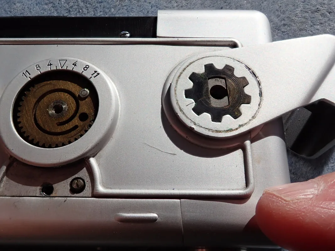
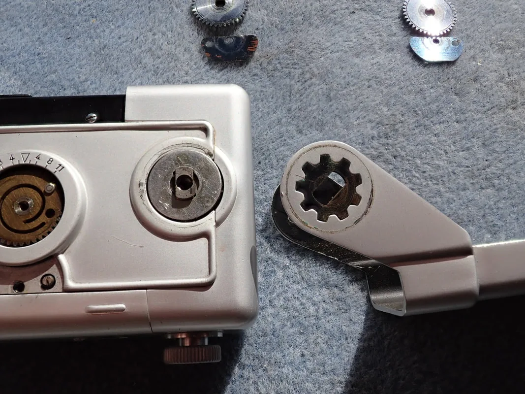
- Fit the shutter control and the focus wheel.
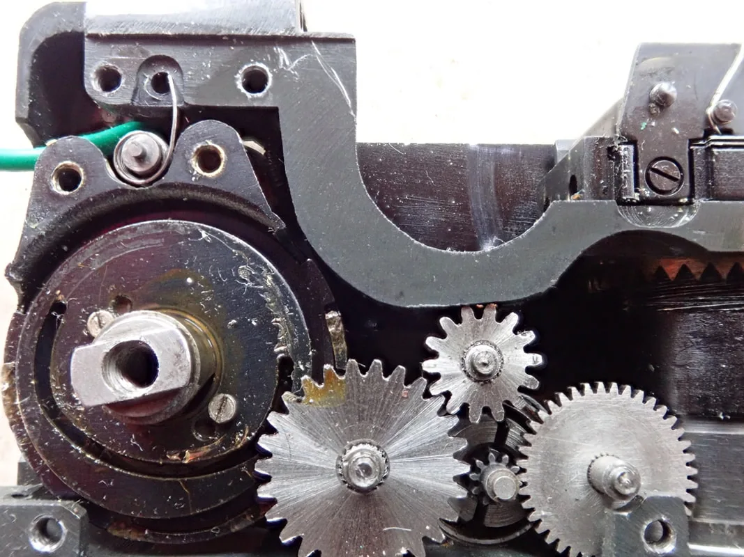
- Fit the exposed gears that drive the shutter control and the focus wheel. Both have end-stops, which must sync with the positions of the control wheels, so some trial and error may be needed so the movements start and stop at the right points.
- Inner (black) front cover.
- Outer cover / winder, including the various washers on each side. The spring should be fully wound at the point that the cover is fitted, so that it can deliver the three exposures that one wind is intended to provide.
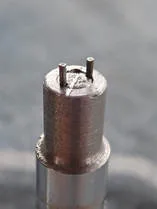
The 3mm driver
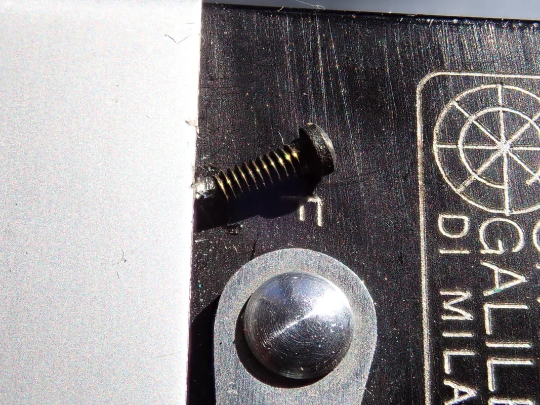
Left - The only bodge - and it is quite a messy one! Are other Gami-16's like this?
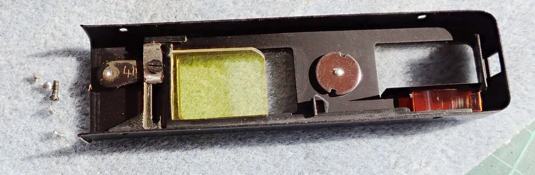
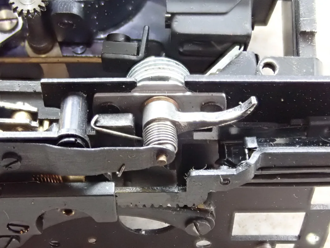
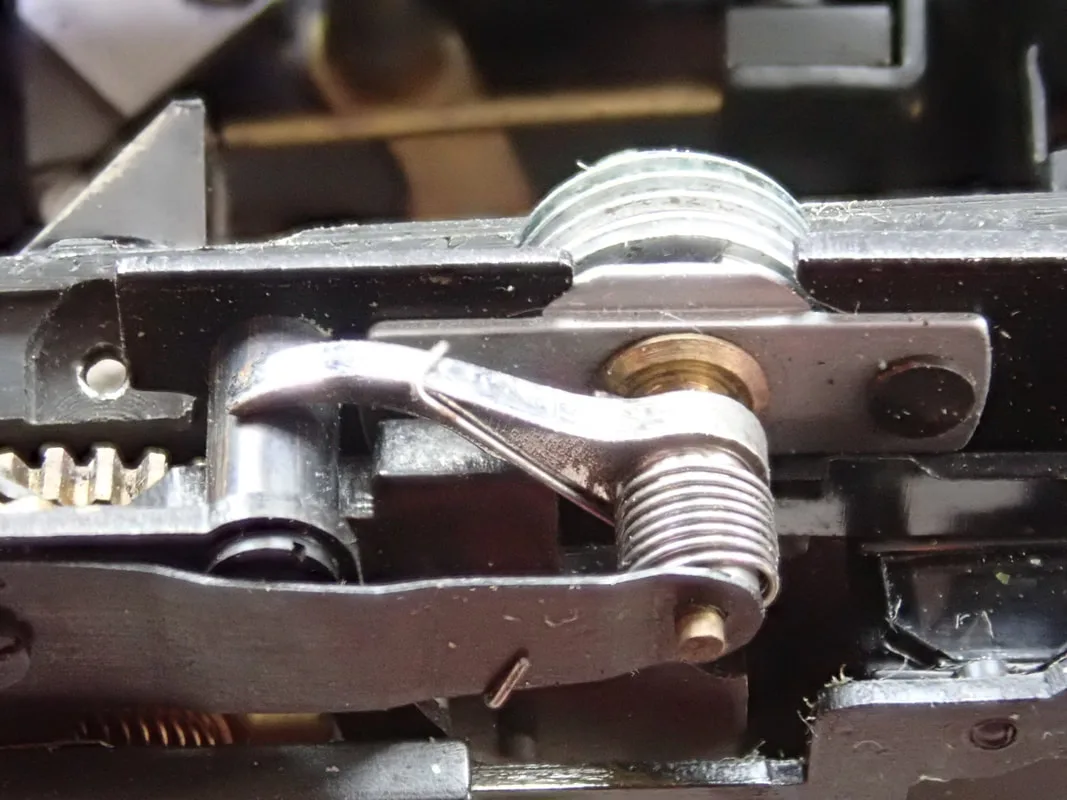
Above left, the disconnected spring which was the cause of all this work. On the right, reconnected in a moment!