Restoring the QRS-DeVrie Kamra
This article is based on a discussion of the Ellison and QRS versions of the Kamra, published in Photographica World No. 165, 2020/2. Since then I have been able to make more progress restoring the QRS version of this very early 35mm camera. I begin with a summary of the history, before going into the ups and downs of bringing it back to life.
And ups and downs there were. I thought it would be interesting to illuminate not only the results, which may be useful to others working on examples of the Kamra, but also give an insight into my restoration process. I had no repair manual – it’s superficially a simple camera after all – so I was working it all out as I went along. Looking back, I could have followed a much straighter path, but this time I’m admitting to all my mistakes and back-tracking!
And ups and downs there were. I thought it would be interesting to illuminate not only the results, which may be useful to others working on examples of the Kamra, but also give an insight into my restoration process. I had no repair manual – it’s superficially a simple camera after all – so I was working it all out as I went along. Looking back, I could have followed a much straighter path, but this time I’m admitting to all my mistakes and back-tracking!
Where it all started - The Ellison Kamra
From the American Cinematographer, January 1927:
“Another Creco Innovation
Make use of your SHORT ENDS OF FILM, don't throw them away. The one hundred per cent efficiency of Kamra for fool proofing locations, settings, etc., etc., will pay for the original cost many times plus.
CRECO, INC., have secured distribution rights to the Ellison Kamra. They will be ready for distribution September first. The price is twenty-seven fifty ($27.50).”
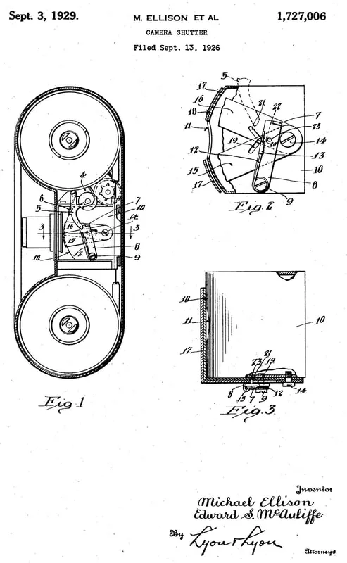
Michael Ellison and Edward McAuliffe of Chicago filed a patent application in 1926 for a two-blade shutter, which was eventually granted in 1929. The blades are operated in a simple scissor style, driven by a pin in curved slots which act as cams. The blades of the “scissors” are bent down at right angles, so the working part moves out and in again, in an arc uncovering the light path. All this is built onto a cast aluminium block which also holds the lens. The shutter provides just one speed.
This shutter is triggered by an arm controlled rather cleverly by a cam, rotated by the operating crank. One full rotation winds the film; when the turn is complete the cam follower drops into a slot, from which a slight reverse movement can release it. A spring then drives the arm to fire the shutter.
The QRS Kamra
It seems that within a few months of the launch of the Ellison Kamra, the design was taken over by another Chicago firm, the QRS Company. The Ellison Kamra company faded away and was eventually dissolved on 19th January 1935, having for two years failed to pay its taxes to the State of Delaware.
QRS were manufacturers of player pianos and their music rolls, and it is easy to imagine that by 1928 business was declining, and they urgently needed something new to do. The answer was photography, and the coming idea of miniature photography using 35mm film. And here in Chicago is a product, maybe needing some more investment and marketing. So in 1928, less than a year from its launch, the Kamra has moved to a new home with QRS.
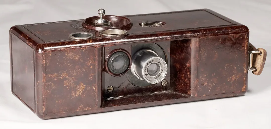
In due course I found and bought a QRS Kamra. Same product name, different manufacturer, and also a different design. And more frequently seen today than its earlier brother. It uses the same shutter mechanism – not just in principle, but mostly the same parts from the same source. The overall camera, though, is significantly enhanced in three ways:
The lens is now a 40mm f/7.7 Graf Anastigmat. A version with a focusing f/3.5 Graf lens with aperture adjustment was also available, but is seldom seen.
The QRS is made of mottled chocolate-brown Bakelite, or a similar plastic. It’s more compact than the Ellison, the width is 18.5cm, down from 22cm. Both are 8cm deep, 6 cm high. As the body is smaller, the bulky cubical cartridges of the Ellison won’t fit; instead we need the rather less bulky D-shaped QRS cartridges. They don’t wind the take-up on a central spool, merely push it in through the light-trapped slot and let it coil itself inside.
- Addition of a frame counter
- Now a T & I shutter instead of just I
- Smaller cartridges allowing the width of the body to be reduced, and holding 1.5m of film for 40 exposures – no longer aimed at using up short ends by cinematographers.
The lens is now a 40mm f/7.7 Graf Anastigmat. A version with a focusing f/3.5 Graf lens with aperture adjustment was also available, but is seldom seen.
The QRS is made of mottled chocolate-brown Bakelite, or a similar plastic. It’s more compact than the Ellison, the width is 18.5cm, down from 22cm. Both are 8cm deep, 6 cm high. As the body is smaller, the bulky cubical cartridges of the Ellison won’t fit; instead we need the rather less bulky D-shaped QRS cartridges. They don’t wind the take-up on a central spool, merely push it in through the light-trapped slot and let it coil itself inside.
Restoration begins
With two versions of the camera, I realised that I had the opportunity to continue the restoration of both. Here I’ll concentrate on the QRS, but work on the Ellison was going on in parallel, and the two sub-projects informed one another considerably. My QRS came without cartridges, and without the crank which does more or less all the operation of the camera. This crank was made of weak cast metal and is almost always broken off in modern examples.
The most difficult operation should have been straightforward. The shutter/lens assembly is built into a cast aluminium block which slides into the plastic body from the back, and is held in place by screws accessible in the front panel. However, undoing the screws left the block still stuck immovably in place. I have come across a problem like this before with zinc diecastings – sometimes these recrystallise, causing them to swell, and become weak and crumbly. Whether in this case the aluminium did swell, or the Bakelite shrink, I don’t know. Either way what must once have been a snug fit had become a dangerously tight one, especially with the inherent brittleness of the plastic body. With careful and patient use of WD40 and gentle heat, I did manage to get it apart without a disaster. I had to file off nearly 0.5mm of metal from the height of the casting, however, before I could reassemble.
The other main job at this stage was to make a new folding crank from scratch, using the style and dimensions of the Ellison as a model – but from brass rather than cast alloy for strength. I nickel plated it – rather badly, the plating is a bit rough, but it looks as if it matches the age of the camera generally so I left it.
With the crank made and some cleaning and fettling of the shutter, the QRS was working, but not yet usable as I had no cartridges. At this point I wrote the article in Photographica World, and included at the end a plea for QRS cartridges ...
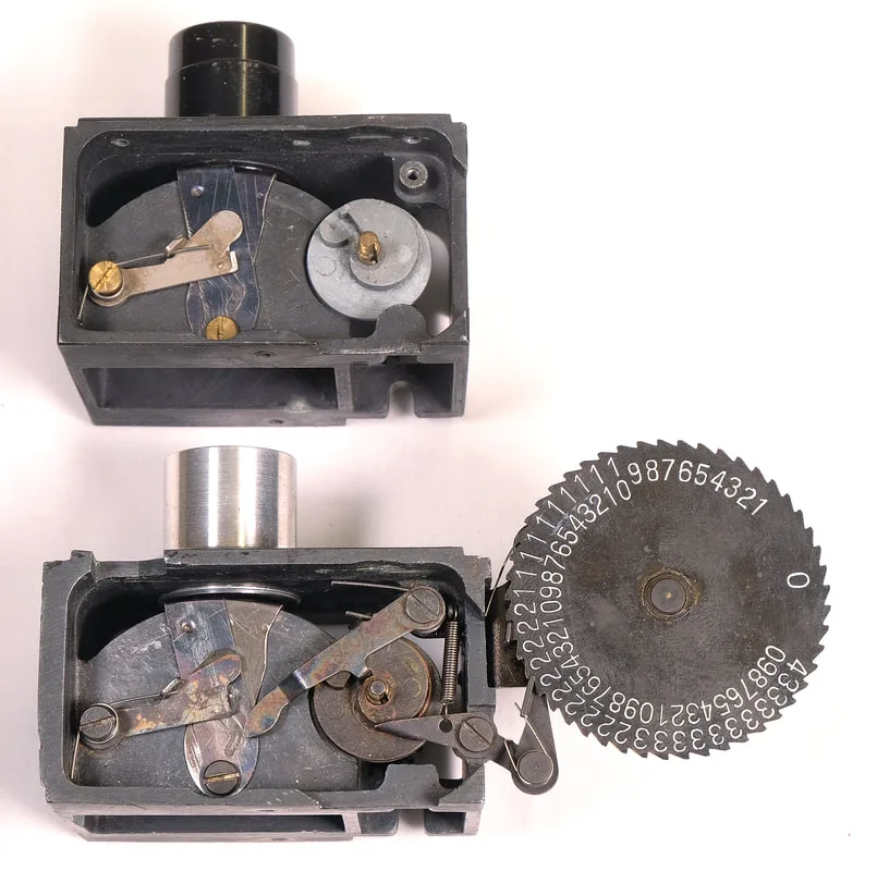
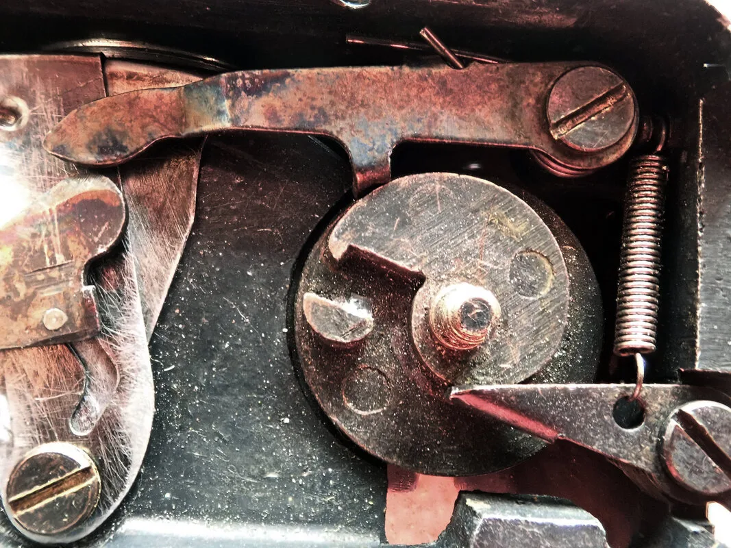
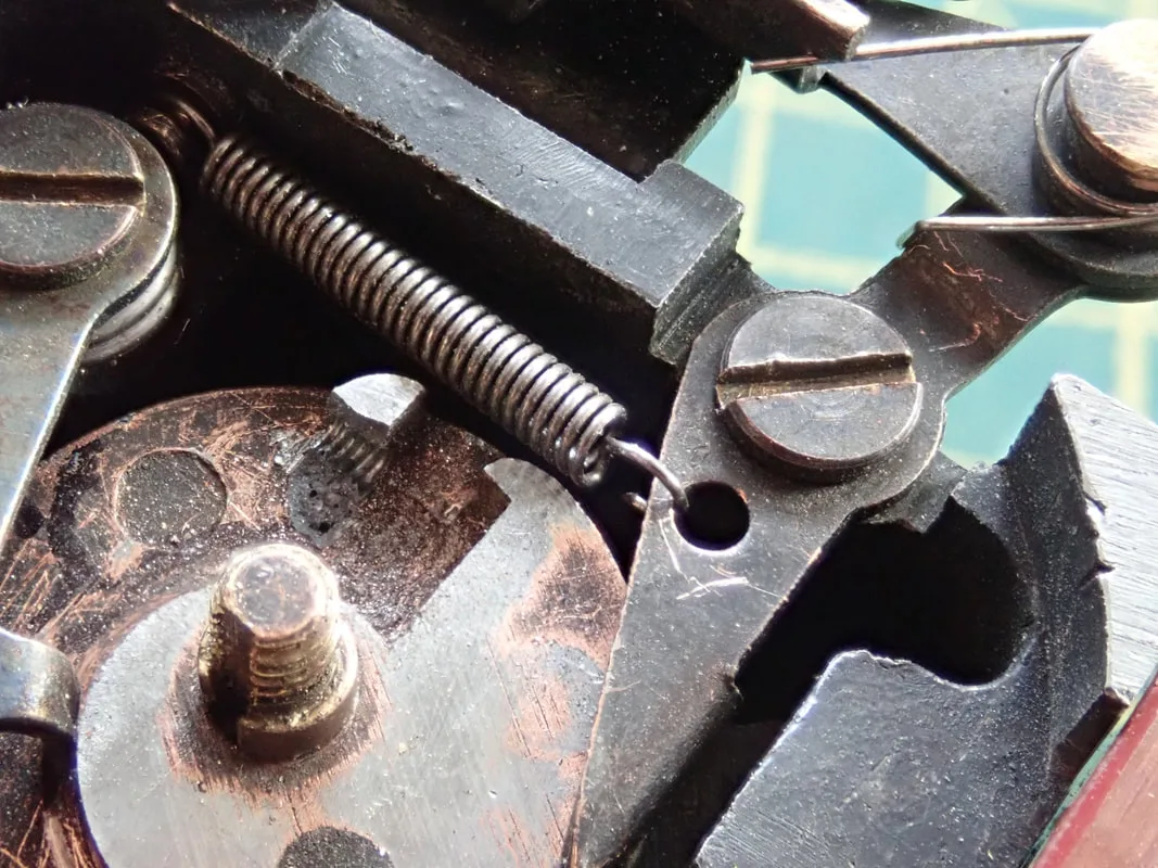
Above - the original mechanism of the Ellison version, cam follower removed to show the clever cam which controls the whole movement.
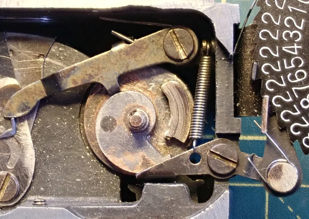
Below - The QRS mechanism has a second cam follower operating a counting wheel.
Note the curved slots in the two shutter blades (the lower one is a mirror image of the visible upper blade). A pin below the left-hand control arm causes the blades to open when it move towards the back of the camera, and close again when it returns.
Restoration Stage 2
... and got an answer from fellow collector Charlie Strizak in Chicago, who lent me a pair of QRS cassettes to copy. I made the new ones from thin brass sheet, shaped around hardwood interior blocks which I made using the dimensions of the originals. The originals were deep-drawn (quite badly), but I can’t do that, so they were made from pieces and Araldited together. They don’t look as neat, though not too bad, and they fit both the space and the film OK.
... and got an answer from fellow collector Charlie Strizak in Chicago, who lent me a pair of QRS cassettes to copy. I made the new ones from thin brass sheet, shaped around hardwood interior blocks which I made using the dimensions of the originals. The originals were deep-drawn (quite badly), but I can’t do that, so they were made from pieces and Araldited together. They don’t look as neat, though not too bad, and they fit both the space and the film OK.
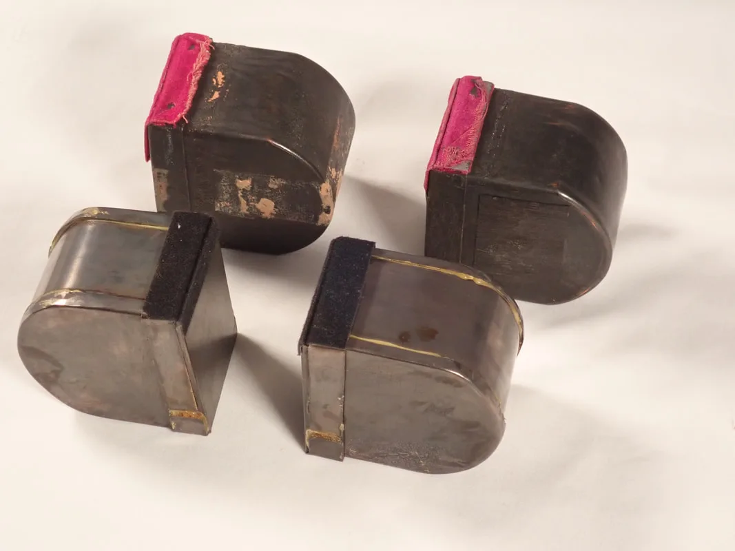
The original cassettes behind, and the newly made ones in front
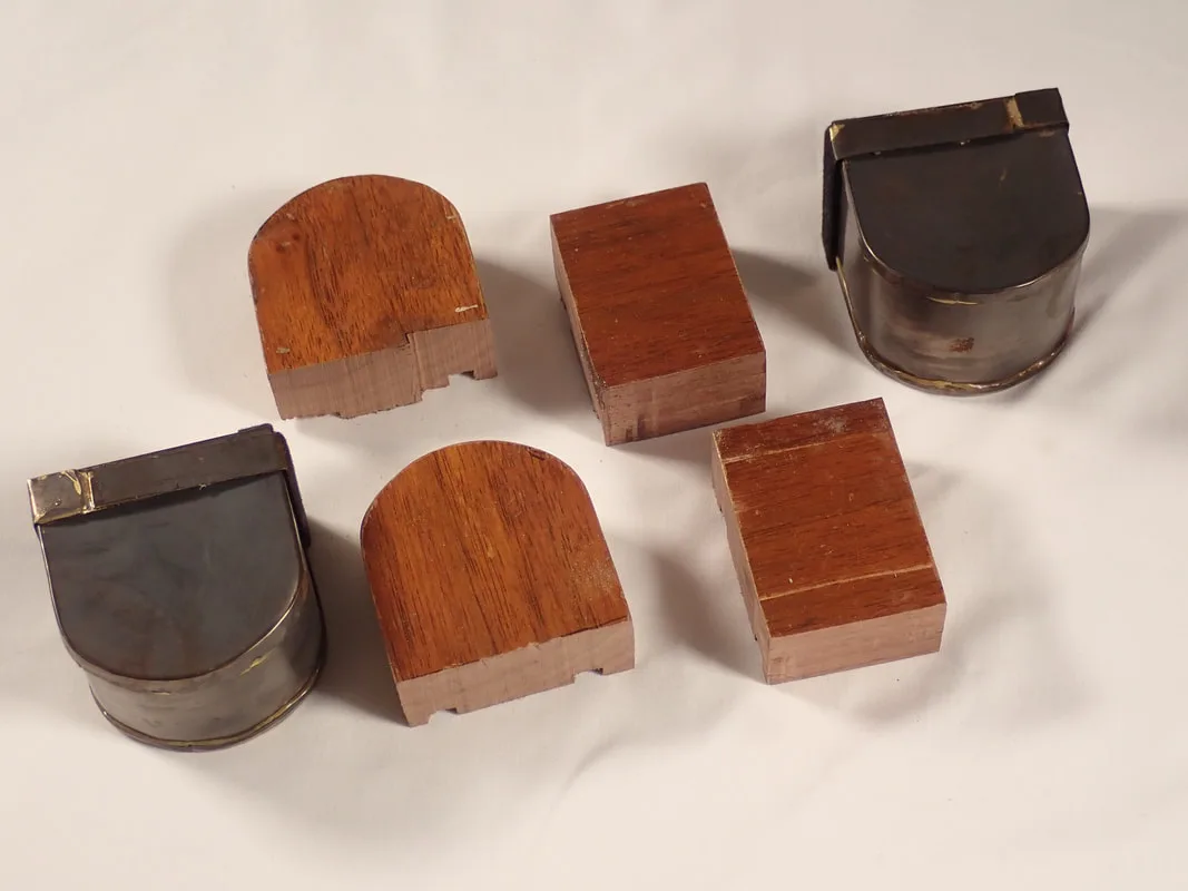
The cassettes were made of thin brass sheet using hardwood formers
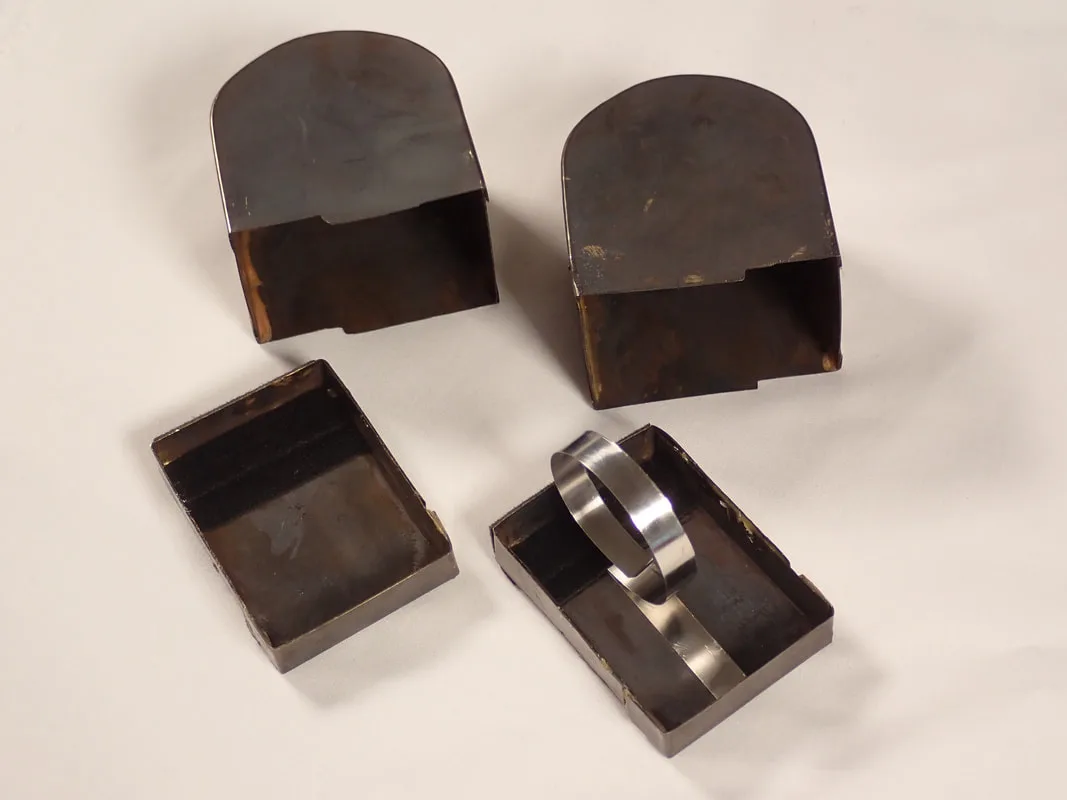
Inside the take-up cassette is a guide spring to encourage the film to roll up
My next step was to try a film through, which soon led me to find that the shutter, serviced by me some 6 months ago, wasn’t working for two reasons.
1. The “scissor” arms weren’t moving smoothly under the pressure of their spring. This turned out to be because I had earlier enlarged the pivot hole of the lower leaf to free it from interference with the edge of the body. However this had made it shift slightly back and forth under spring pressure and jam. The solution was to superglue a shim washer in the right place, and very slightly relieve under the screw head to accommodate the extra space. In the end I also needed to leave the screw undone by about 1/5th of a turn, and secure it with blue threadlock. In retrospect, this experience makes me think that the original mismatch in dimensions between the Bakelite and the aluminium was caused by the expansion of the metal rather than shrinkage of the plastic, as here we had a clear example of a change in dimensions entirely within the metal components. More on this later.
2. I had earlier somewhat increased the spring pressure on the main cam follower. Perhaps because of that, or perhaps it was tired anyway, but the detent cast into the cam at the point just before shutter release had broken off. I tried replacing it with a tiny cuboid of brass, Araldited on, but twice this broke off. Next step was to drill and tap M1.6 through the remains of that support, and let in a grubscrew to serve the function of the detent. That seems to work, though there is a backup plan involving removing the old stump entirely and replacing it with a larger brass plate carved to the right profile – which is designed and ready to go if necessary.
3. Frame spacing was erratic, with frequent partial overlaps.
The broken "tooth" of the cam
The tooth replaced with a little piece of brass - not to last, I'm afraid
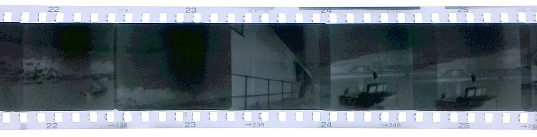
Overexposed and Overlapped negatives
Film Transport
The initial problem is the gearing between the drive shaft and the sprocket shaft being insufficiently engaged. This, combined with rather loose location of the sprocket shaft by the way the guide plate holds it down, caused the gears to skip over one another most or all of the time.
On close inspection, the back surface of the shutter block, to which the guide plate fits, is not flat, but bowed up in the centre as much as about 0.5mm. So I filed and then sandpapered this surface until it was flat, and also slightly eased the two fixing holes in the guide plate (to 3.5mm from 3.2) so they held down properly. This helped the sprocket shaft itself to be held down much better – though the two little pegs that do so are rather crumbly Bakelite, and may not last.
Now a dry run gave correct spacing for the first 20 frames, but what must still be some missed teeth leading to what would be overlapping frames after that.
I also investigated the fact that the back doesn’t fully lock down, it rocks slightly on the tops of the two screws that hold down the guide plate and act as locking pins for the slider that holds the back on. There are potentially several ways to correct this; I chose in the end to spot-face the guide plate 0.6mm down under the screws, so the plate itself stays in the same place but the screw heads and the locking point are both lower. This resulted in the back closing completely as it should.
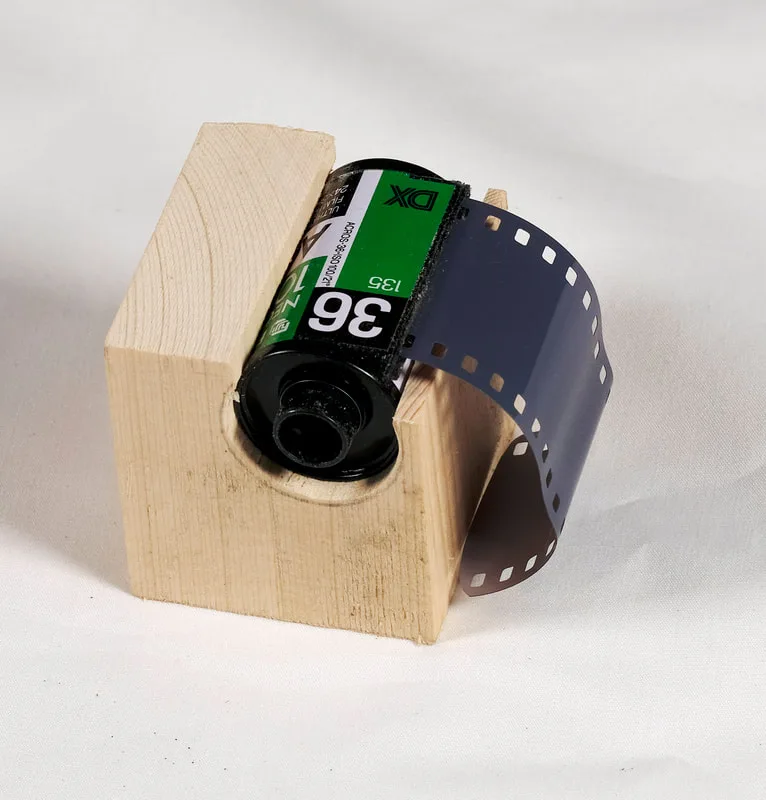
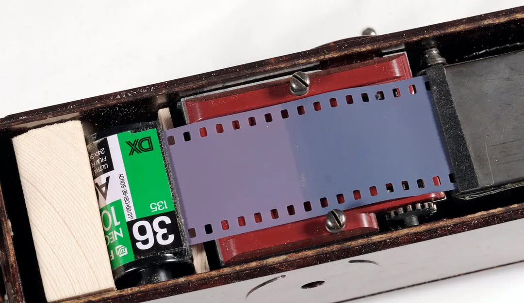
For a trial with real film, I found that a standard 35mm cassette will go in the feed-space, it just needs something to hold it in the right place. So I made a block of softwood and used a cassette of b/w film rather than transferring it to the home-made feed cassette.
Putting in real film revealed some more problems:
1. Continuing tendency for frames to overlap
2. Occasional “crunches” where failure of the film to move properly into the take-up cassette caused (or was caused by) torn sprocket holes, and the film either stopping altogether, or in one case stopping, crumpling, and restarting.
3. The viewfinder view is far from coincident with the actual scene – probably the bottom quarter is cut off in the photo, compensated by extra sky.
4. Gross focus errors. All images were very soft. I made a cardboard mount to put the lens temporarily in a BPM bellows, in which it could be fitted and focused on my Fujifilm X-H1 (register=17.7mm). This showed that when focused at 12 ft (presumed hyperfocal distance) the flange to sensor distance was approx. 47mm. The QRS distance is 43.1mm. So bad, that I dismantled the lens and found that the front element was in backwards [had I cleaned it earlier and done that?!]. Reassembled correctly and it performs well, with a measured FFD = 43.06mm which looks correct.
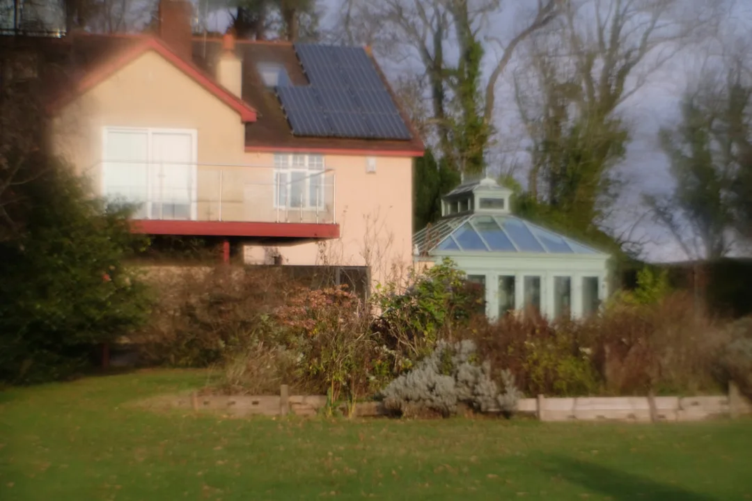
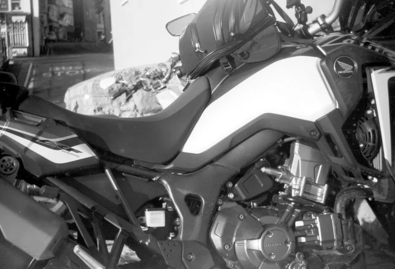
Image made by the Graf lens with the Fuji X-H1 and BPM bellows
Same setup after rebuilding the Graf lens with the correct orientation of the front element. In both these pictures the lens was focused to get the best result, but remember that in the QRS it is fixed at 10-12 feet.
At this point the main cam failed! After a few dozen operations the metal into which the grub screw had been inserted, broke off. This cam is the heart of the whole camera, and is also made of dodgy cast metal. Although in principle I could make a complete new one, either traditionally or by 3D printing, it would be fairly difficult, and anyway I want to preserve as much of the original as possible.
So I implemented Plan B, which was to make a rather larger than original brass piece (more glue surface) for the stop that traps the cam follower to make the exposure. In the process of fitting and fettling that, more broke off the cam. I glued it back, and reinforced the lower surface by Aralditing on two layers of steel shim washer (0.2mm each) and let it set for a couple of days. After this the shutter seems reliable, and does 1/30th. Sometimes it doesn’t quite close, leaving a little slit; but not often.
Also at this point I further investigated film transport. There was still too much vertical play on the shaft that carries the film sprockets, and it turned out that the guide plate didn’t sit perfectly flat on the (flat) casting. I inserted a 0.5mm shim at the input end of the guide plate to tilt it over, which made the other end of the plate sit lower over the sprockets, and they are now well constrained. Tests showed that now the film runs without buckling, as the sprockets engage more consistently and push it better.
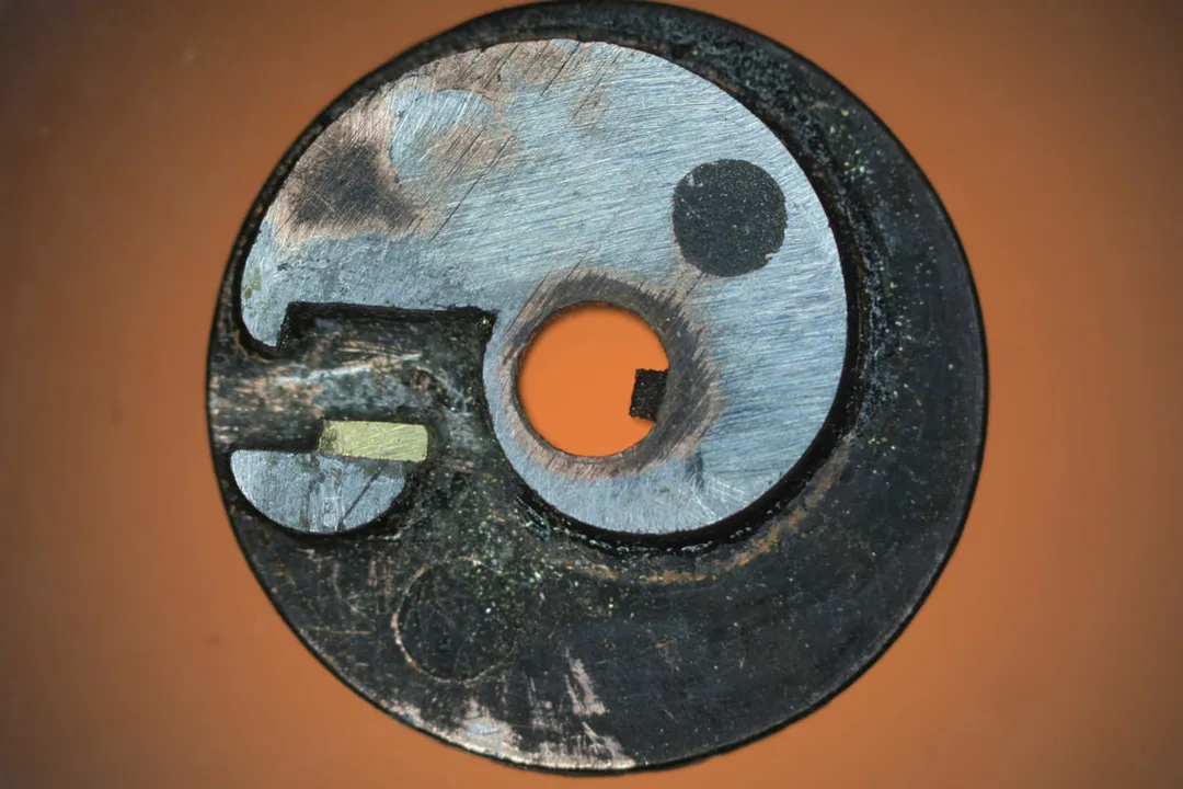
The rebuilt cam has a much larger "tooth", designed to spread the forces of use over a much wider area of the base of the cam, and still allow all the levers to move where they need to go. There is also steel reinforcement on the lower surface.
The temporary grub screw was too stressed for the cast tooth, most of which has broken away.
Another roll of film now. Ilford Delta 100 with a yellow filter, exposure reasonable in winter sun. A whole 36-exp roll went through without big transport problems. The lens is now focusing reasonably well, best at around 10 ft. Remaining problems are:
1. The shutter is not closing perfectly, so most frames have a vertical light leak down the centre, worst in the sky area – i.e. the lower, free, end of the shutter blades.
2. Still some but not all frames overlap at the ends – basically one skipped sprocket hole. This seems to be associated with some interference of the rotation of the operating crank at one point in its cycle, which I can feel as I operate the camera.
3. It is very hard to avoid camera shake!
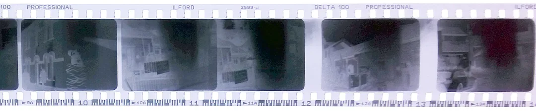
Above - the negatives from this trial, some overlapping and most with a light leak where the shutter failed to close completely.
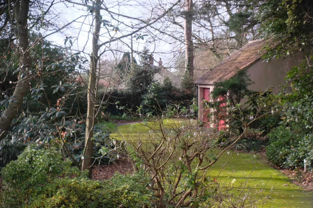
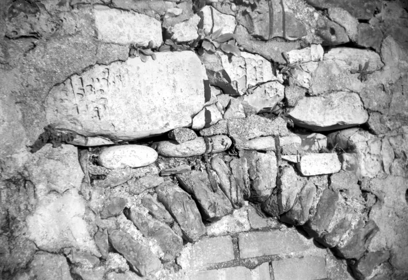
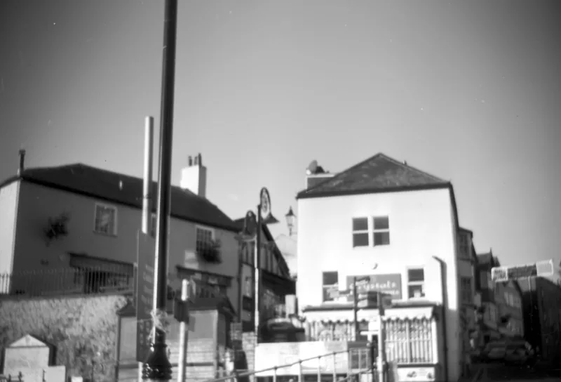
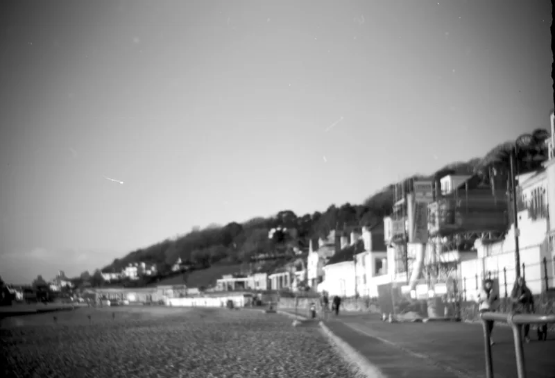
Right - A typical positive from this series.
Right - A typical positive from this series.
The main thing to do now was rebuild the shutter blades. The problems of the shutter all go back to the original issue of the apparent distortion of the aluminium casting. The “scissors” of the shutter fold down over the curved front of the body casting, and the centre of rotation is at the back. As the casting expanded, this distance increased causing the shutter blades, especially the inner/lower one, to bind as they touch the front of the casting instead of just clearing it. The change we are talking about is small – around 0.1mm (0.004") – but enough to stop things working smoothly. I had previously freed the inner shutter blade by very slightly enlarging the pivot hole, but it turned out that this caused another problem that I should have foreseen, that under the influence of the cam pin in the driving slot, this back bearing now being loose allowed the blade to shift sideways and stick. I cured this eventually by gluing on a very thin steel shim washer of the right size, but not quite on the original centre so as to allow freer movement.
Suddenly the shutter movement became much sweeter, and seems to work every time.
The other thing to do was to track down the interference at the operating crank. The top sprocket on the sprocket shaft runs extremely close to the bottom surface of the main cam, which was repaired earlier. I found a tiny burr that was catching the sprocket once per rotation, and filing this off cured the interference.
The viewfinder mirror – a piece of chrome plated steel sheet – had been rattling around loose when I got the camera. I had held it in place with a dab of glue, but clearly not at quite the right angle. After a few trials that didn’t get it sitting properly, I made a little wooden wedge at exactly 45° to sit underneath it, held that in with double-sided tape (in case it needed to come out again) and taped the mirror to the wedge. Still not perfect, but close and probably as good as it ever was.
Another test
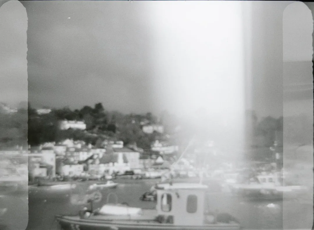
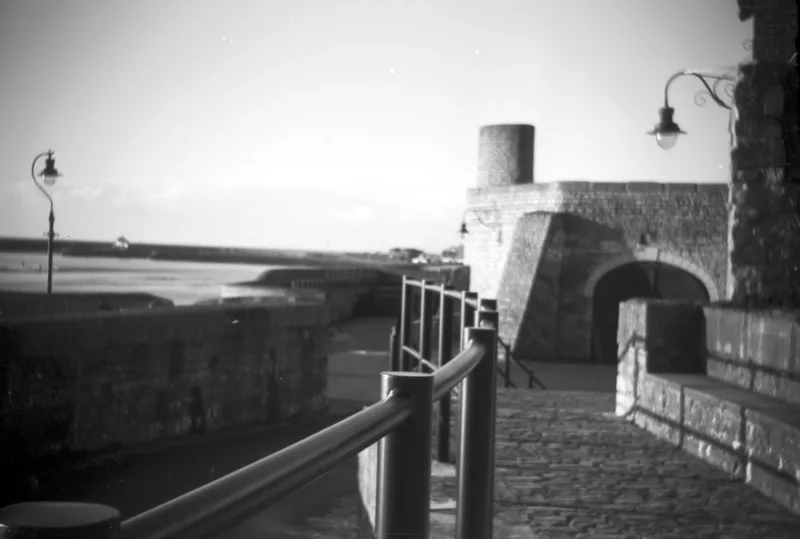
In bright conditions this camera is suffering from a mismatch between its design and the speed of modern films. It was intended for regular use with much slower film than we mostly use now. So I looked around for a slower alternative, also seeking more contrast from this not very good optical system; the solution I picked was Washi-S, described here in my December 2020 blog. As well as its photographic properties, it is on a strong, stiff but thin polyester base which lies very flat, and feeds particularly well in the “push” system that the QRS uses. I filled a piece of this this into the newly-made feed cassette, so this time was using as close as I can get to the original QRS setup.
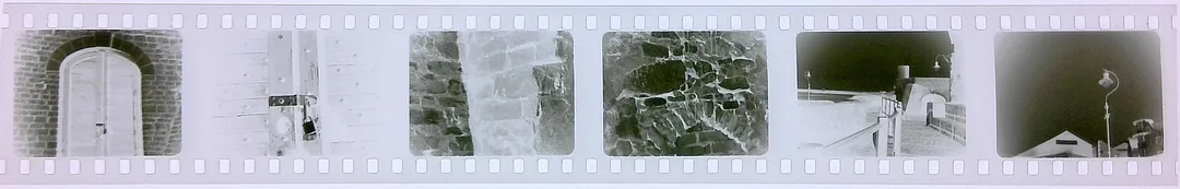
At last, now a reasonable result which probably gives a fair idea of how the QRS performed when new - see the examples below. Finally I get pictures which are all evenly spaced with no misfeeds and no light leaks (including none from the earlier shutter problem). What remains is the actual performance of the camera, its shutter and lens.
Suddenly the shutter movement became much sweeter, and seems to work every time.
The other thing to do was to track down the interference at the operating crank. The top sprocket on the sprocket shaft runs extremely close to the bottom surface of the main cam, which was repaired earlier. I found a tiny burr that was catching the sprocket once per rotation, and filing this off cured the interference.
The viewfinder mirror – a piece of chrome plated steel sheet – had been rattling around loose when I got the camera. I had held it in place with a dab of glue, but clearly not at quite the right angle. After a few trials that didn’t get it sitting properly, I made a little wooden wedge at exactly 45° to sit underneath it, held that in with double-sided tape (in case it needed to come out again) and taped the mirror to the wedge. Still not perfect, but close and probably as good as it ever was.
Another test
In bright conditions this camera is suffering from a mismatch between its design and the speed of modern films. It was intended for regular use with much slower film than we mostly use now. So I looked around for a slower alternative, also seeking more contrast from this not very good optical system; the solution I picked was Washi-S, described here in my December 2020 blog. As well as its photographic properties, it is on a strong, stiff but thin polyester base which lies very flat, and feeds particularly well in the “push” system that the QRS uses. I filled a piece of this this into the newly-made feed cassette, so this time was using as close as I can get to the original QRS setup.
At last, now a reasonable result which probably gives a fair idea of how the QRS performed when new - see the examples below. Finally I get pictures which are all evenly spaced with no misfeeds and no light leaks (including none from the earlier shutter problem). What remains is the actual performance of the camera, its shutter and lens.
Conclusion
Now it is working, how good a camera is it? I think users would have been disappointed for several reasons
- It is large and rather heavy, despite holding only enough film for 40 exposures.
- Despite the bulk it is not easy to hold steady. I found a tripod more or less essential, or at least a monopod. The operating crank is not in a convenient position for handling, and contributes to the camera shake problem.
- The lens vignettes quite badly.
- Although the negatives will bear a small enlargement, as soon as you look more critically at them you realise that distant scenes such as buildings and landscapes are very out of focus. The lens is set to focus at about 10 feet, and the aperture of f/7.7 gives a depth of field which is acceptable close to, but fairly hopeless for scenery.
This is a camera that would have benefited from the general availability of faster film, which would have allowed the lens to be stopped down. That in turn would have given better depth of field, sharper pictures and a larger image circle. As it was, users were probably not very impressed with their results, in turn explaining the short production life and low sales. The QRS does have a serial number (mine is marked Series No. A / 5338). I have seen online serial numbers from 1xxx to 16xxx, so at least 16,000 were probably produced either as the QRS or as the QRS/DeVry (there had been yet another takeover, but the Kamra continued basically unchanged). There was also a version with a focusing and aperture-adjustable lens, potentially a more usable camera with control over exposure and depth of field – and hopefully a better lens with a bigger image circle. However, I think very few were actually made.
This short-lived group of cameras made their small contribution around 1928 to the deluge of 35mm cameras which were to come along in a very few years’ time. Not even an influential design, but certainly a harbinger of things to come.