- Published on
Mercurial Batteries on a tight Budget
- Author
-
-
- Name
- Posts
- Posts
-

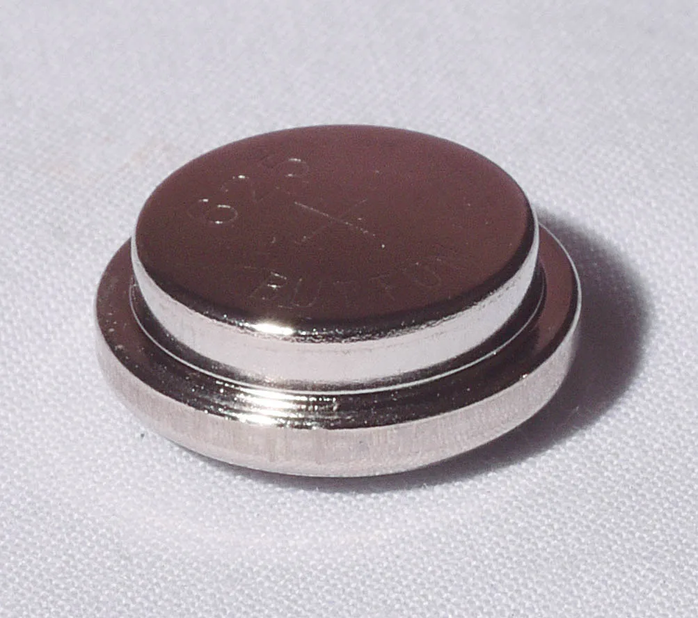
As we all know, the traditional mercury battery has long been discontinued, and substitutes have to be found to power many cameras and exposure meters of the 1960s. The commonest battery of the time was the PX625, aka PX13 or LR9. A large number of alternatives are on offer, many of them rather expensive, so I thought I would have a go at a bare-bones solution. I have relied heavily on the published work of Frans de Gruijter who has analysed the problem in depth, and offers a neat kit to convert the shell of an old 625-size battery to carry a silver oxide cell to produce the necessary 1.35V.
The nub of the issue is that to keep the circuit cheap, most designers at the time relied on the fact that a mercury cell gives a nearly constant voltage all its life before dying suddenly, so the meter could rely on the battery to give a fixed known output. The electronics could then consist of nothing but battery, LDR (light dependent resistor - the light-sensitive CdS or CdSe cell), meter and one resistor, all wired in series. It’s that simple!
So what other cells give the constant voltage we need and are still available? Several, is the answer, but easily the best for us is a silver oxide cell which gives a nearly constant 1.55V. You can put one of these directly in a meter but it is likely to read too high by several stops, and be non-linear. We need to reduce the battery voltage by 0.2V, and the way to do that is a suitable diode (a Schottky diode) which creates a voltage drop of 0.2V, that itself is also constant; a resistor would give a voltage drop proportional to the current flowing, which would not do at all. The diode is wired in series with the battery.
This is the conclusion reached by Frans de Gruijter, and is the basis of his conversion kit – which I have tried and can recommend. But maybe we can slim it down even more? Here goes.
The slimline adaptor is a paper disc with a conducting layer each side, with the diode soldered to the edge of each layer. This slips under the battery, with the diode near the edge of the compartment, where the shape of the battery leaves a little space. The pad itself is less than 0.5mm thick and should not cause any clearance problems in the instrument. If your device needs two batteries, you also need two adaptors.
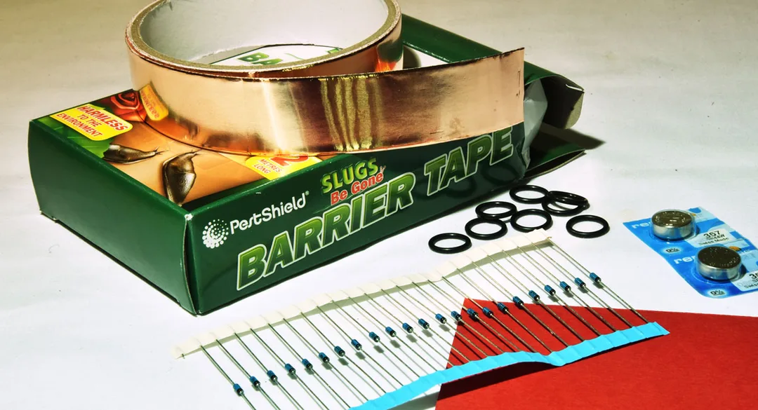
Materials needed:
- 300gsm red card – 60p for an A4 sheet at our local art shop.
- Self-adhesive copper foil. This is sold in garden centres to deter slugs. A roll 22-25mm wide and a couple of metres long costs about £4. The copper is very thin, and is supported on backing paper. Enough here for hundreds of adaptors, or use the rest for its intended purpose!
- Schottky diode – Type BAT-46 is readily available and suitable. I bought a pack of 25 for £3.52 from eBay – 14p each.
- Battery – silver oxide type 357 (aka SR44) – priced between 50p and £1.50 each depending on brand and source.
- Electronic solder with incorporated flux.
- An O-ring 11mm ID x 14mm OD, may be useful to keep the battery centred in the compartment, depending on the details of the design of the camera / meter.
So someone wanting to make half a dozen adaptors to fit a few devices, could buy the necessary for £10-12 and still have spare materials for future use. The battery itself is by far the biggest expense, of course. When it needs to be replaced, the adaptor can be re-used. However, the adaptor is relatively fragile, being made of paper, thin foil, and a tiny glass-bodied diode. So it might have an accident; however, if you have bought materials in the quantities mentioned, you can make a replacement adaptor without battery for about 20p.
Tools needed:
Most of the job can be done with readily available hand tools – a craft knife and scissors are useful, tweezers, small snipe-nose pliers, and a fine-tipped soldering iron. The trickiest part is probably the punching out of neat discs of paper and backed copper foil, best done with wad punches. These can be bought individually, or as a set of punches with a common handle. You need two sizes – either 3/8” and 7/16” or 10mm and 11mm would do. Expect to spend around £20 if you need to buy these. I happen to have a small hand-press which does a good job of punching out these materials. But usually you would use a block of wood and a hammer, and you need to give the punch a surprisingly meaty thump even when just cutting paper.
Most of the job can be done with readily available hand tools – a craft knife and scissors are useful, tweezers, small snipe-nose pliers, and a fine-tipped soldering iron. The trickiest part is probably the punching out of neat discs of paper and backed copper foil, best done with wad punches. These can be bought individually, or as a set of punches with a common handle. You need two sizes – either 3/8” and 7/16” or 10mm and 11mm would do. Expect to spend around £20 if you need to buy these. I happen to have a small hand-press which does a good job of punching out these materials. But usually you would use a block of wood and a hammer, and you need to give the punch a surprisingly meaty thump even when just cutting paper.
Construction sequence:
Cut a piece of the red card to approximately the width of the foil tape, and stick down a length of the copper foil, to cover one side.
Using the larger punch, punch out as many discs as you like. A piece of material 8”x1” should make 20-odd discs. Each disc should be completely covered with copper on one side, and bare card on the other.
Using the smaller punch, punch out the same number of discs directly from the copper foil plus its backing paper. This should give you a set of discs with the copper on one side and still on backing paper.
Using the tweezers, lift the copper from these smaller discs one by one, and stick them to the bare card side of the larger discs, trying to keep an even margin of red showing all the way round. I call this side of the card the positive side. You need to be sure not to get a short-circuit between the copper pads on the two sides of the card.
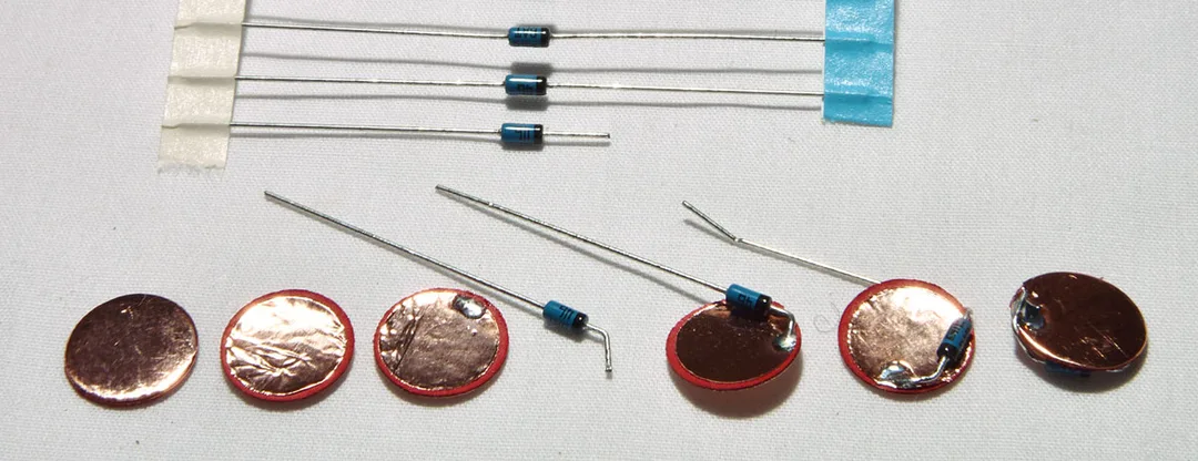
Now for each disc:
With the soldering iron, make a little dot of solder just at the edge of the positive pad.
Take a diode, and note the black ring round one end. Trim that lead to about 6mm long. Hold the lead with fine-pointed pliers, butted up to the diode, and bend it about 70°. The reason for the pliers is not to do the bend at the actual end of the diode body, which is fragile.
Hold the diode by the other lead, so that it is positioned on the edge of the disc, over the red rim, roughly parallel to the edge, and with the end of the short lead over the little solder dot you made. Solder lead to dot (only a couple of seconds contact at most, so the diode doesn’t get overheated).
Using the thin pliers as before to protect the diode body, bend the second lead up and around the edge of the disc, so it lies flat and in close contact with the edge of the negative pad. Trim off the excess lead and solder in place, rapidly as before.
That’s it done.
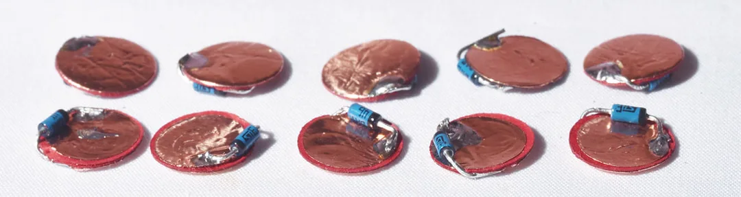
Back row, negative side up - front row, positive side (red ring) up
Is it working?
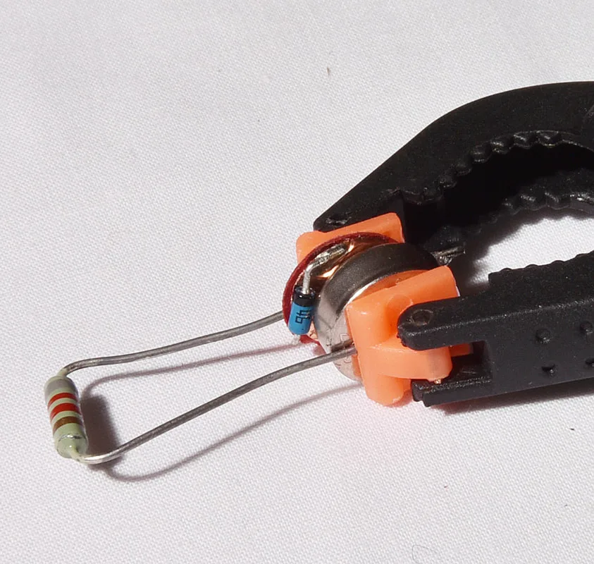
If you have a digital multimeter you might want to check your work. As well as the meter you will need a resistor to allow a small current to flow during the test – the voltage drop created by the diode won’t appear without a little current. The value of the resistor is not critical, but something in the region of 10kΩ will be fine. Use some kind of clip or clothes-peg to clamp together the battery and the newly made disc, with the resistor to complete the circuit. The positive face of the pad should be in contact with the negative face of the battery. Now measure the voltage across the test resistor. Likely results:
- About 1.3V – success!
- About 1.5V, same as the battery on its own – a short-circuit between the two pads of the adaptor.
- About 0v – damaged diode, or the wrong way round.
Installation and use:
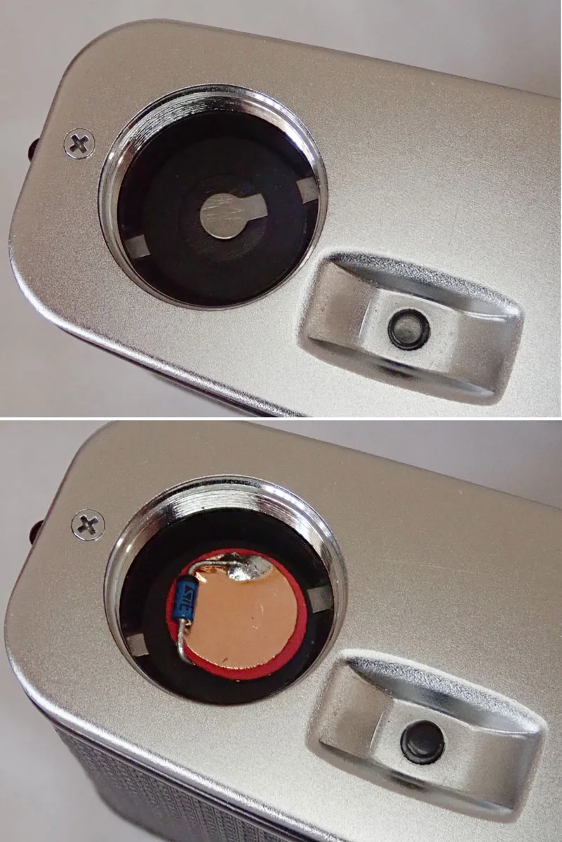
The battery compartment of your camera or meter will usually have a spring contact in the bottom (negative), space for one or two cells, and a screw-on metal cap (positive) which retains everything and completes the circuit. Drop an adaptor in first, make sure the red ring is visible – i.e. positive side up. It should cover the spring contact, but leave the diode near the edge so it doesn’t get crushed. Put an o-ring on the battery if it seems to help centre it, and drop the battery on top, positive side up. Screw on the cover.
If your device needs more than one battery, it will need an adaptor for each. Electrically it doesn’t matter what order they all go in, but for physical fit I recommend alternating batteries with adaptors. Trying this with a Gossen Lunasix, that was easily the best way to go, and produced accurate readings.
That should be it. Try the meter, comparing it with a known good one if possible. As the optical characteristics of meters vary, they may not agree exactly but should be close. Try both high and low light levels. When the battery needs replacing, look after the adaptor – it can be re-used indefinitely so long as it is not damaged.
Great work!