|
The low-contrast developer POTA is excellent for getting normal contrast results and a wide dynamic range when using inherently high-contrast films such as Tech Pan and (nowadays in my case) Washi-S. However it is a bit awkward to use as you need to make it up and let it cool each time, then use it immediately or it will go off.
The components of the working solution are 30 g/l Sodium sulphite and 1.5 g/l Phenidone. Normally you dissolve the sulphite in hot water, then dissolve the Phenidone in the same solution, and cool it before use. The Phenidone is always reluctant to dissolve and the usual advice is not to worry about a bit being left undissolved, which I always think is a bit untidy. What I do know, though, is that Sodium sulphite solution is reasonably stable on its own, and Phenidone dissolves easily in alcohol (ethanol) and seems to keep at least for months as a 15g/l solution in ethanol. I have a licence to use small quantities of "Industrial Denatured Alcohol" as it is called in the UK, which is what I use for this. It is better than the regular domestic methylated spirit as it doesn't have a dye or pyridine (smell) added, and it is reasonably dry - the domestic spirit has some water in it. I haven't tried either domestic methylated spirit for this developer, or isopropanol, but they might work. Further experiment needed there. Here is my experimental formula based on all this: Make two separate stock solutions - Solution A is 150 g/l Sodium sulphite (anhydrous) in water Solution B is 15 g/l Phenidone in alcohol. Both of these should keep for a few months and possibly more. To make a working solution, for each 100 ml ... Take 70 ml water at about 25°C Add 20 ml of A and mix well Add 10 ml of B slowly, mixing as you go. The result should be a clear pale yellow liquid, or maybe slightly cloudy which is still OK. It should also be at about 20°C, if not, next time adjust the temperature of the starting water. Use immediately. Typical development time is 12 minutes with normal intermittent agitation in a tank, adjust to suit your own conditions.
0 Comments
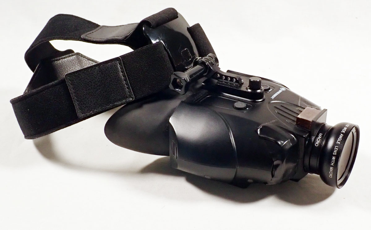
I frequently find myself wanting to work on panchromatic film in the darkroom. I may need to re-spool it, cut it to a smaller size, process it by hand, and so on. In the past I have had to do this entirely by feel, which is possible but often tricky and frustrating. Photographer Christopher Creighton remarked that he uses an infra-red (IR) viewer to do such work. What a brilliant idea! The particular viewer that he uses is one originally made as an accessory to a video game, and it’s only occasionally available used on eBay in the UK; and quite expensive too. So I thought I had better start from scratch and see what I could find. Illumination We want illumination that doesn’t fog the film, but will register on the viewing apparatus. To plan that, we need at least an approximate understanding of the spectral sensitivities of film and viewer, and the emission spectrum of the illumination. 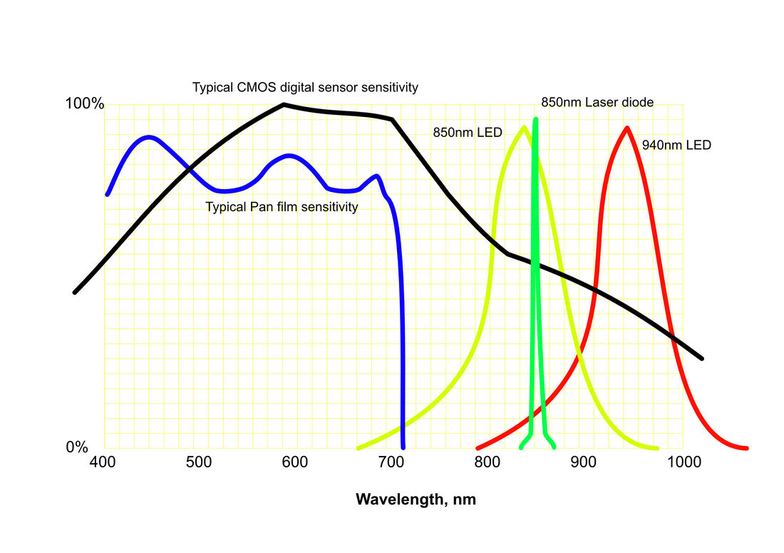 The graph sketches the possible relations between the components of the IR viewing system. The range of human vision is approximately 400-700 nm (nanometres) and panchromatic film (blue line) matches that reasonably closely. The near infra-red (IR) extends from 700 to about 1200 nm, which is the region we want to use. The sensor in the viewer is likely to be CMOS (black line), which has good though declining sensitivity in this region. In the graph are the outputs of possible IR illumination. What we need is plenty of light emission in the region where the viewer’s sensor can operate, but none in the region where the film we are working with is sensitive, because that would fog the film. The commonest IR illuminators work at 850nm, but as you can see (yellow line) there is some overlap with the film sensitivity around 700 nm, so the film will be fogged to some extent. There are three possible solutions:
This is all a little simplified and a small amount of unwanted light may still exist, so the aim must also to be to limit the brightness of the illumination, which will maximise the length of time that film can be exposed before generating significant fog. The test I do is to try to get about the right brightness of the “lamp” (a little board with an array of 940 nm LEDs), as seen by my viewer, then leave a piece of film face up in the darkroom for 30 minutes with the IR lamp on, and a penny on the film so that fogging is distinguishable from any inherent fog from the film and processing. My LED board is for 12v DC, has 48 LEDs working at 940 nm, and is much too bright. However you don’t have to drive it at 12v, it will work with anything from about 7v upwards – 9v is convenient as suitable power supplies are common. I also mask off most of the LEDs leaving just 6 visible. I place this a metre or so above the workbench, reflecting off the white ceiling, and a 30-minute exposure doesn’t fog the film.
I did also try an 850nm laser torch – as above, laser diodes have a much narrower bandwidth than LEDs and so should not emit wavelengths close to the limit of sensitivity of the film. This also worked, not fogging the film in 30 minutes; but it is a more expensive solution and is no better than the 940nm array. A further option I didn’t try would be to get a piece of sharp-cut IR filter to subtract the tail of the emission from 850nm diodes. This material does exist, but so far I have only found suppliers of industrial quantities, with minimum orders which make it uneconomic. Viewer Thinking about the viewer, there are quite a few requirements for something that will actually be usable:
On that basis I found a viewer, binocular so-called but not really, made by a German firm called Bresser. It is one of the relatively few that don’t magnify, and there is almost no video lag. It is made for 850 nm and has two IR lights. It works in normal light too, and at first I thought that I just needed to turn off the built-in IR lights to use it with a separate illuminator. However that’s not the case; the IR switch not only turns on the lights, but also changes the settings of the sensor. To achieve IR sensitivity you have to turn on the built-in IR illumination, and for this application mask the lights with something opaque.
I made other adaptations too. It is 1x magnification, and focuses easily as close as necessary. The width of the scene is still insufficient though, so I bought a wide-angle adaptor x0.45, made to clip onto a mobile phone. I cut off most of the spring clip, and glued the part that the lens screws into, to the front of the Bresser. The Bresser’s rubber hood is too small to accommodate normal reading glasses, but the very narrow “pocket” ones do fit. I had to mask off one of the lenses of the reading glasses to avoid double vision. I did try a sheet of plastic Fresnel magnifier instead, but prefer the glasses. IR light is safe in these quantities, there is plenty of it in ordinary daylight. IR torch lasers, like other lasers, need to be treated with care – don’t look into the beam. High-power IR lasers should not be used, and anyway are quite unnecessary for this purpose. Costs I’m trying to keep the costs down of course. I have spent, in late 2022:
So for under £150 I have a system that allows me to work for a good length of time manipulating panchromatic film, including aerial survey film with extended red sensitivity, and see what I’m doing. By the way, do not use this with actual IR film which would certainly be fogged. On the other hand I don’t see any reason why I couldn’t use it with normal colour negative and transparency materials. There seem to be continuing online questions about how to select the correct gears for Cirkut cameras, depending on focal length and focal distance. By inspecting the scales on the bed of my Cirkut #8, I find that there is a simple straight-line logarithmic chart for each distance and all focal lengths. 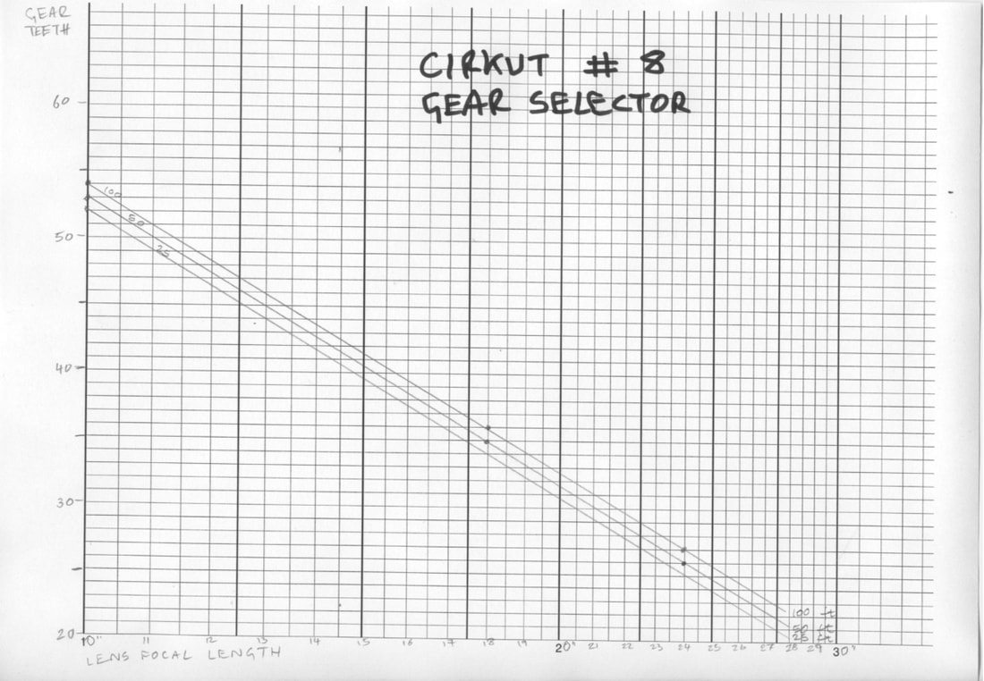 Note that the x-axis scale is logarithmic and the y-axis is linear. However there is no need to worry about any of that. Choose your lens focal length (in inches) along the x-axis, then the y-axis shows the tooth count of the required gear at 25, 50 or 100 ft. I guess infinity uses the 100 ft setting. A larger PDF version is downloadable from the link below. It would be a useful exercise to check the data for other Cirkut models, but I don't have those so leave it to others - who may hopefully to publish the results!
Gear Design If you don't have a gear to use as a model, here is a basic drawing. Any small lathe will be suitable. 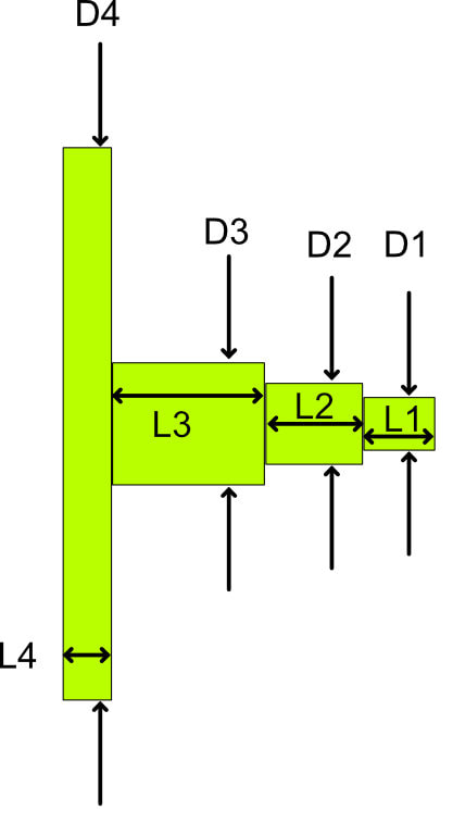 Dimensions:
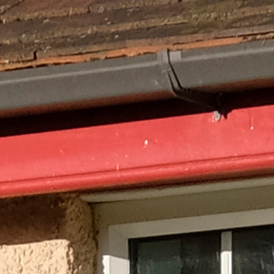
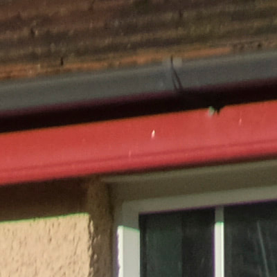
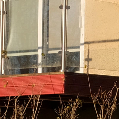
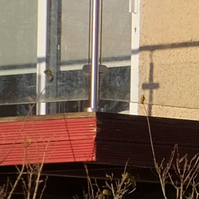
D1 - turn to 4.1mm diameter then form a screw thread #8 UNC over the full length. L1 - 5.5mm D2 - 6.3mm nominal, but should be a sliding fit inside the gear socket of your motor. L2 - 7.3mm D3 - 9.5mm in the original, but can also be any convenient larger diameter. The right face of this section positions the gear the correct distance below the motor. L3 - 11.5mm in the original but see below D4 - this is the gear itself, so the diameter will vary by tooth count. Use Module 0.8, PA20° (which is the default) L4 - 3.75mm in the original. L4 is the thickness of the actual gear blank, and the gear you buy or make may be different, typically thicker. 3 - 5mm thickness should be no problem, if more it is probably best to face it thinner. The shaft and gear will be made separately, so the shaft will have a projection to the left to fit the bore of the gear, typically 6mm. If the gear comes with a boss, the diameter of the boss will displace a good part of D3/L3. If there is no boss, be extra careful to get the gear truly square to the shaft when you attach it. In the original I think the shaft is a press fit to the gear, with the left end peened over to be sure. I find that with a good fit, soft solder or a modern adhesive are both fine - the gear is not highly stressed in service. The key to getting the gear at the right position against the big toothed wheel of the tripod head is getting the total of L3+L4 correct. These dimensions are as original for my Cirkut #8 but I have another original Cirkut gear whose shaft was about 9.5mm longer before I cut it down to fit this camera, so it's clear that there is more than one standard size. Washi-S Development Trials Having a need for a 35mm film suitable for testing several quite old cameras, I though I would try Washi-S. It is a specialist emulsion, fine grained, sharp and fairly slow, intended for recording optical sound-tracks for the cinema. It's a 50 ISO film, a bit like the old Kodak Tech Pan but more tractable, supposedly, and it is Pan/Ortho (limited red sensitivity). For cameras of this age - around the 1940s and earlier - the speed should be compatible and the high contrast could compensate for a rather low-contrast lens. That's the idea, anyway. I got mine from Analogue Wonderland. Reading up on it, everyone agrees that for pictorial purposes the contrast needs to be tamed, and of course there are many opinions on the best way to develop it. There is wide (but not universal) support for Stand Development, using a whole range of possible developers, each with its own enthusiastic supporters and detractors. In the hope that these are perfectionists, I did trials with what I had to hand! Method – dilute developer, vigorous agitation at the start, then none. Tanks sat in a bowl of water at 20°C to hold temperature and discourage convection. For the trial I exposed three short lengths of the film in a Nikon FE2 with its 55 micro lens, so the sharpness and the exposure should be assured. Scanned with Vue-Scan, multi-exposure on, 3200dpi. Trial 1 Subject – the S side of the house in full December sun. Contrasty conditions. Developers - Rodinal 1:100, PC-TEA 1:80, Ilfotec HC 1:100 (1+3 then 1+24). 45 min. Results: Rodinal – no image, just some faint brownish fog at the hyper-exposed film end. PC-TEA – Best result; a contrasty neg, bright and sharp. See my August 2018 blog for more on PC-TEA. Ilfotec HC – nearly as good as PC-TEA but more contrast, and significant burnout in highlights. Conclusion: PC-TEA is the most promising, but has too much contrast. Overdeveloped. Trial 2 Developer - PC-TEA again, but 1:100 this time and less than half the time. Subject – various test cards, interior shots. Also two exteriors, in dull even misty conditions, far lower in contrast that the previous sunny ones. Developer – PC-TEA 1:100, 20min stand development at 20°C. Scanning as before, though the multi-exposure made no difference this time. The positive scans of the test cards show that the darkest 4 blacks out of 19 are the same black, so not perfect for shadow detail, the other patches are well distinguished. No grain, generally smooth tones without development artefacts, though a few small roundish fuzzy areas of lighter tone (in the positive). The scans mostly need a modest amount of lightening in post, but otherwise look good. Conclusion The result of Trial 2 is good enough to try on a real old camera (the Nikon FE2 doesn't count as one of the old ones, I used that for its reliable shutter and metering, and good lens.) I have been restoring a 1928 QRS Kamra, reported here amongst my other restoration projects, and used this method for the final tests. 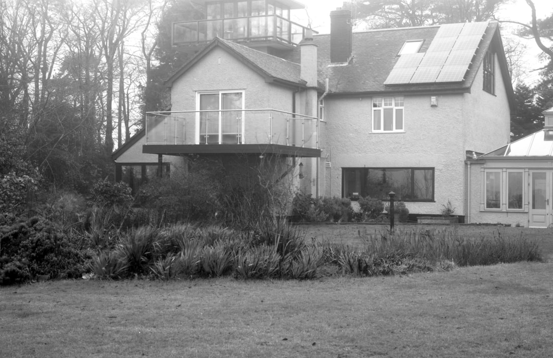 House on a misty December day. More on Developing Washi-S
I have recently had good success, better than the previous methods described, using the POTA formula originally devised for processing Kodak Technical Pan. POTA is very simple, but doesn't keep, it should be used immediately after it is put together. However it is very simple to make: The formula is 30 g/l Sodium sulphite (anh.), 1.5 g/l phenidone. The phenidone is not keen to dissolve in water, so I make a separate solution in Industrial Methylated Spirit (= Industrial Denatured Alcohol). It might also work in other lower alcohols such as methanol or isopropanol, perhaps also in ordinary domestic methylated spirit, though that tends to have significant water contamination,. I haven't tried any of those myself. So I make a solution of phenidone in the alcohol, 15 g/l. it dissolves easily and keeps at least for weeks in a dark glass bottle. My procedure for 1 film in a tank requiring 330ml of developer is:
See my June 2023 post for more on this!
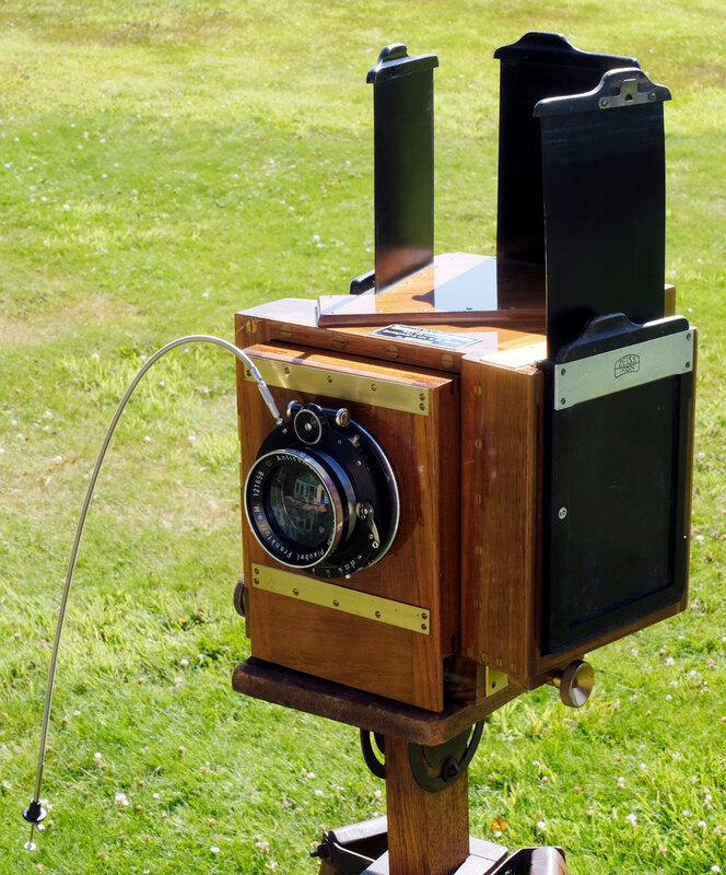
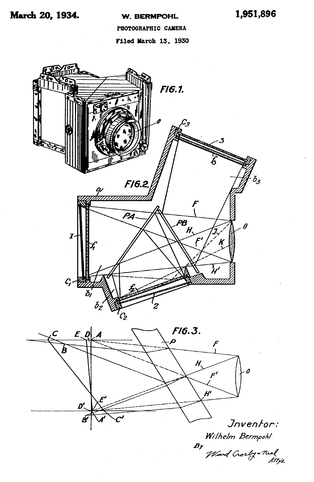
The Anticomar lens is not the original spec, though the FL and aperture are suitable. A Meyer Doppel Plasmat f/4 was usually fitted. The attachment of the Anticomar’s mounting ring is far below Bermpohl standards, and previous screw holes show it to be a replacement. I put a torch inside in the darkroom, and found quite a big light leak around where the lens flange fits to the lensboard. The flange is non-original and not properly fitted, the spigot is several mm smaller than the hole, so no surprise. I found a ring in stock that fits the spigot properly, machined a relief in the wooden lensboard in the lathe using the 4-jaw chuck, so now the lens flange connects light-tight to the panel. The focusing rack is quite stiff; it also locks. It’s immediately obvious that the groundglass image is dim, and will need care to set up. The camera is also very heavy and needs a solid tripod, in my case a Gandolfi with its platform. If you look through it with all the filters removed, the image at each window is of course dim - it is also far from neutral in colour, being brownish. On closer inspection the mirror nearer the lens transmits orange (minus blue), and the one further back transmits green. This is all part of the method of suppressing unwanted internal reflections - but surely the filters should do that anyway? All this light loss raises quite serious problems; the instructions recommend exposing 25x as long as a simple camera in the same position - my experiments suggest that's optimistic, and around 40x is preferable. For ISO 200 film, that means exposing at about ISO 5. I have been making modified darkslides, and working out a suitable exposure and processing regime. The camera came without darkslides, but I had a set of 3 ZI double darkslides which I could fit with some careful wood trimming and insertion of adaptors for sheet film. All that is now sorted, as is the elimination of light leaks and some preliminary trials of exposure. Focus: The GG is 4.2mm back from the reference surface, and the film in the (non-original) darkslides is 6.2mm back. The short term fix is to move the lensboard backwards 2mm after focusing.
 There are various defects - the registration of the three negatives isn’t perfect, which seems to be down to the internal alignments of the camera, and the colour rendition is noticeably non-uniform across the scene. That’s partly because the first mirror is not perfect, some of the silvering has suffered a bit of mechanical damage. And the depth of field is insufficient for the depth of the scene. Nevertheless, it is all quite encouraging, and begins to show why for a while this approach was quite popular with professionals, mainly for portraiture and advertising. Apparently nearly all Bermpohl’s output went to the USA, mainly to studios that produced luxury advertisements. The three negatives could of course be worked up directly into printing plates. I guess the next step will be to go outdoors where exposure will be easier to manage. Choice of location and subject will be tricky; obviously a colourful subject, but it needs to be in a readily accessible space. The camera is so heavy, and despite that I suspect not very robust, that I can’t just chuck it in the back of the car and go looking! I suspect that they were seldom taken from the studio, though I’d think there were bound to have been at least some beach/fashion pictures taken in 1930s California. My trials will be less demanding. A note on post-processing:
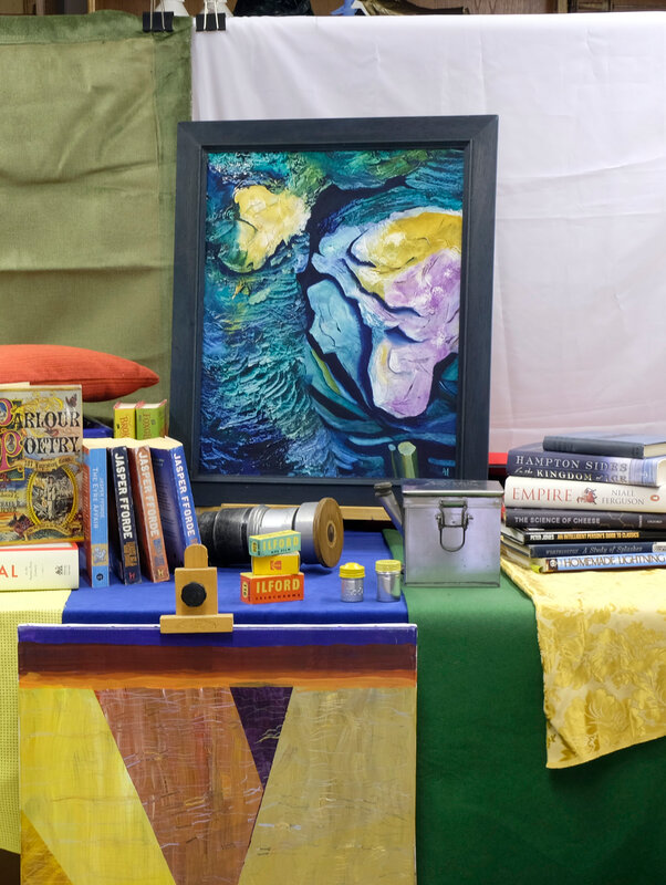
The product of each shot is a set of three monochrome negatives recording the primary colours in the scene. These days, they must be scanned and assembled in the computer to produce the colour image required. I use Affinity Photo for this, which does it easily: If possible include at least a greyscale in the picture. Do the initial scans and flip so all are the right way round, and positive. Preferably scan all three as a single operation and then split them, to get correctly proportioned exposures. In Affinity Photo: Import the three images as a "live stack" with alignment. Copy the three layers of the stack, paste them above the live stack, delete the live stack. Make sure you are in RGB mode. Select the R layer, go down to Channels, find the R layer’s own channels. Right click the G and B in turn, and clear them. Repeat appropriately for the other two pixel layers. Select all 3 pixel layers and change the blend mode to lighten. Tune the individual colours with a Curves layer dedicated to each pixel layer. A good starting point seems to be to adjust the various greys (dark, med, light) so the colour picker shows reasonable balance between the channels for all. Finally another Curves layer above all, to tune up the overall result.
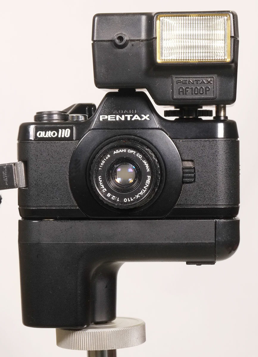
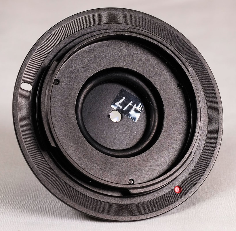
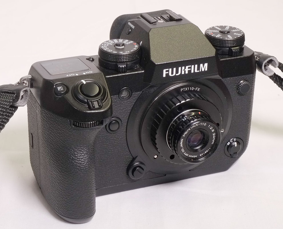
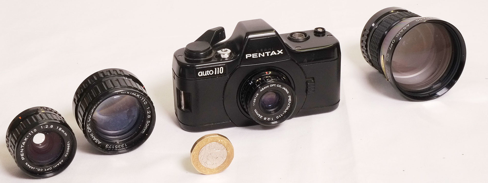 Pentax 110 outfit - camera, dedicated flash, and four lenses; 18mm, 24mm, 50mm, and 70mm, with a British pound coin for scale.
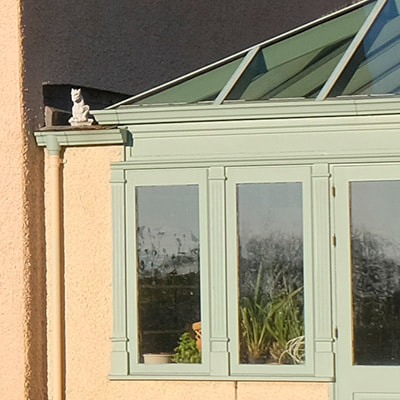
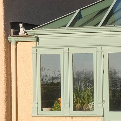
So now on to trying out the P110 lenses on the Fuji camera. All the test pictures were taken of the same scene, on a tripod in the same position. We start with a picture of the scene taken with the Fuji's own lens - the 16-50mm zoom set at 24mm and f/7.1 - to give an idea of what a modern system makes of it:  And now with the P110 24mm standard lens, using the f/7 washer. The white box shows the crop corresponding to the Pentax's actual image size: 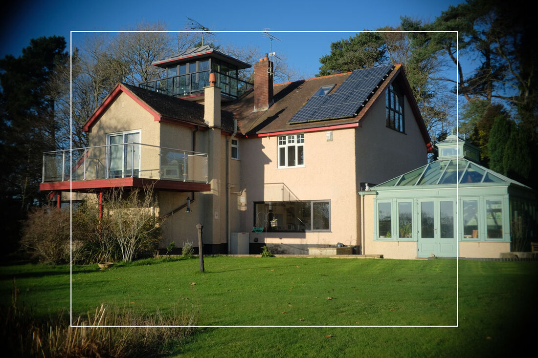 There is serious vignetting and loss of sharpness at the edges, but it barely extends into the area that the lens is intended to cover. We see the same thing with all the lenses, not surprisingly at its worst with the wide-angle 18mm. Expanding to 100% we can see that the modern lens (16-50 zoom at 18mm) and the Pentax 18mm perform very similarly within the intended coverage of the Pentax lens (both at f/7):
The same can't be said of the 70mm Pentax lens, which seriously underperforms the Fuji 55-200mm zoom set at 70mm:
At 50mm this problem goes away, with similar results from the Pentax and the Fuji zoom at its 50mm setting:
The final comparison is with the standard focal length of 24mm (Pentax) and the 16-50 Fuji zoom set to about 24mm, which gives us:
... this time the Pentax is not quite up to modern standards, a little softer and less contrasty - but a respectable performance even so for a lens of its period. I conclude that the Pentax lenses, with the exception of the 70mm, are remarkably good for 40-year-old designs, and can stand up well to a comparison with modern expectations. Although not ideal for APS-C because of their limited coverage and the need therefore always to crop, they should do well on a Micro-4/3 digital body. I would avoid the (rare and expensive!) 70mm, and was particularly impressed with the tiny 18mm lens. Remarkable!
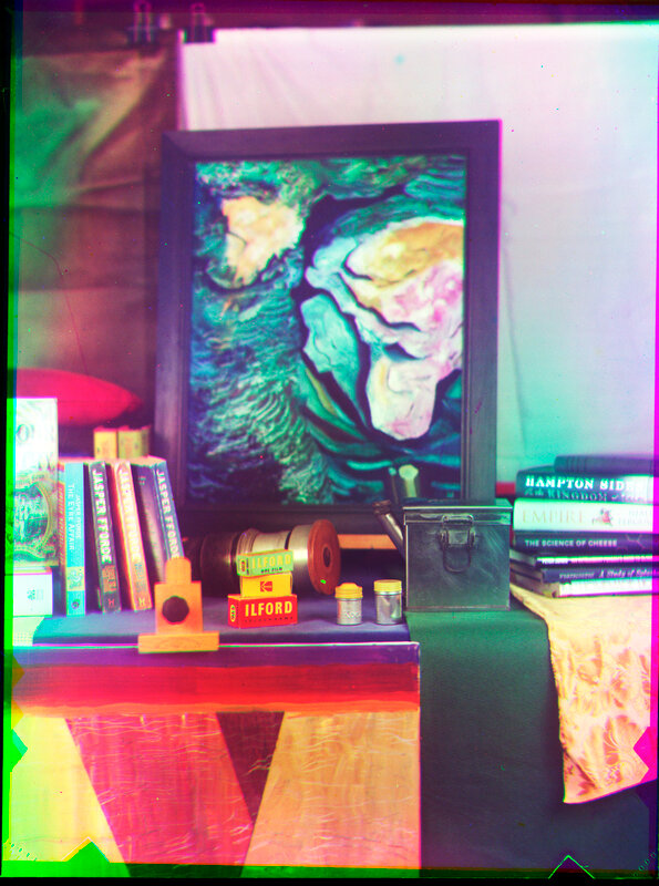
I'm in the midst of preparing a talk on cameras which take photographs through mirrors. I don't mean mirrors in viewfinders and rangefinders, to qualify they must take the actual picture through one or more reflections. So this includes such things as stereo accessories which fit on the front of an SLR lens, mirror lenses themselves (catadioptric lenses) and many others. One of them is the ever-amazing Polaroid SX-70. This does indeed use a mirror to reflect the final image that's recorded, but even more fun is the optics of the viewfinder, so I took a picture of that using a semi-dismantled scrap SX-70, a laser pointer and a judicious touch of artificial smoke. 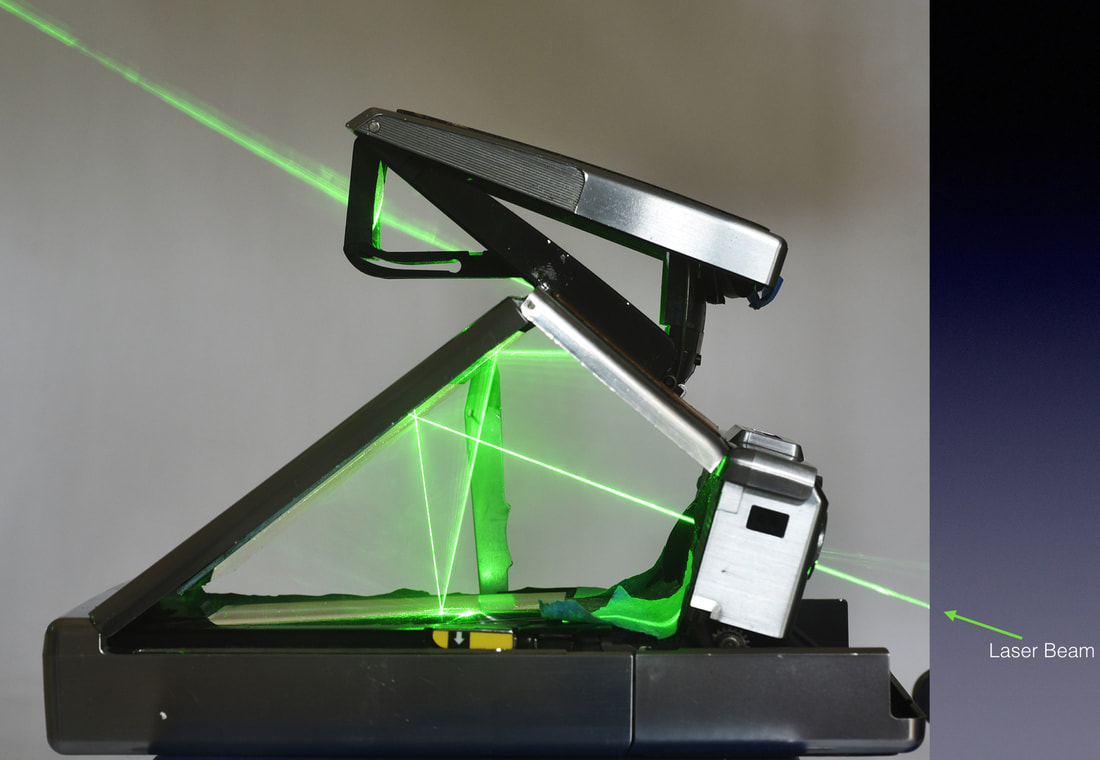 The beam enters lower right, passes through the main lens, reflects in a plane mirror down to a fresnel mirror (with split-image rangefinder feature) which is on the upper surface of a movable flap, presently covering the filmpack. From there it is reflected back to the upper mirror again, and across to a concave (magnifying) mirror in the viewfinder housing. From there it passes through the viewfinder lens and on to the eyepoint. When the shutter release is pressed, the flap carrying the fresnel mirror swings up to cover the sloping plane mirror. There is another plane mirror on the underside of the flap, so we still have a mirror under the large sloping surface of the camera. The light coming in from the lens is thus reflected downwards to the now-uncovered film surface. And still in focus, because although the mirror is now a few millimetres lower, because of the thickness of the flap, the receiving surface is also a few millimetres lower - presumably all calculated to be an equal distance!
Although I have seen diagrams of this before, I have never seen it in live action like this, so I thought it should be shared.
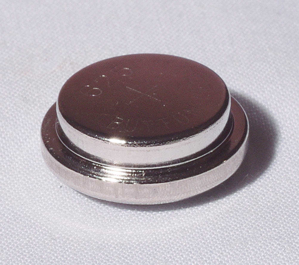
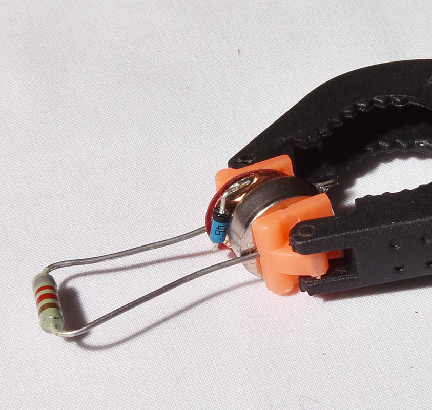
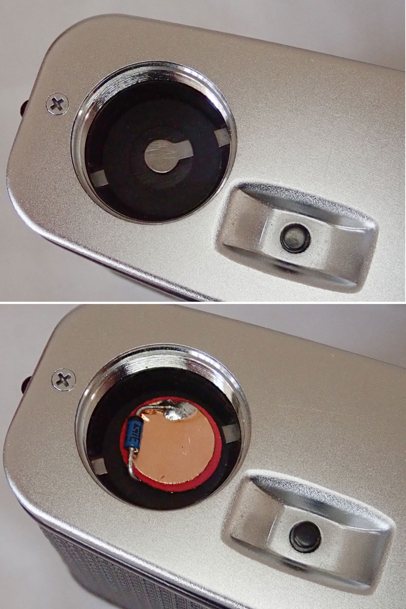
The nub of the issue is that to keep the circuit cheap, most designers at the time relied on the fact that a mercury cell gives a nearly constant voltage all its life before dying suddenly, so the meter could rely on the battery to give a fixed known output. The electronics could then consist of nothing but battery, LDR (light dependent resistor - the light-sensitive CdS or CdSe cell), meter and one resistor, all wired in series. It’s that simple! So what other cells give the constant voltage we need and are still available? Several, is the answer, but easily the best for us is a silver oxide cell which gives a nearly constant 1.55V. You can put one of these directly in a meter but it is likely to read too high by several stops, and be non-linear. We need to reduce the battery voltage by 0.2V, and the way to do that is a suitable diode (a Schottky diode) which creates a voltage drop of 0.2V, that itself is also constant; a resistor would give a voltage drop proportional to the current flowing, which would not do at all. The diode is wired in series with the battery. This is the conclusion reached by Frans de Gruijter, and is the basis of his conversion kit – which I have tried and can recommend. But maybe we can slim it down even more? Here goes. The slimline adaptor is a paper disc with a conducting layer each side, with the diode soldered to the edge of each layer. This slips under the battery, with the diode near the edge of the compartment, where the shape of the battery leaves a little space. The pad itself is less than 0.5mm thick and should not cause any clearance problems in the instrument. If your device needs two batteries, you also need two adaptors.
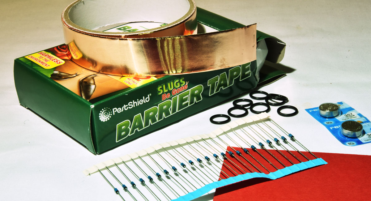
Tools needed: Most of the job can be done with readily available hand tools – a craft knife and scissors are useful, tweezers, small snipe-nose pliers, and a fine-tipped soldering iron. The trickiest part is probably the punching out of neat discs of paper and backed copper foil, best done with wad punches. These can be bought individually, or as a set of punches with a common handle. You need two sizes – either 3/8” and 7/16” or 10mm and 11mm would do. Expect to spend around £20 if you need to buy these. I happen to have a small hand-press which does a good job of punching out these materials. But usually you would use a block of wood and a hammer, and you need to give the punch a surprisingly meaty thump even when just cutting paper. Construction sequence: Cut a piece of the red card to approximately the width of the foil tape, and stick down a length of the copper foil, to cover one side. Using the larger punch, punch out as many discs as you like. A piece of material 8”x1” should make 20-odd discs. Each disc should be completely covered with copper on one side, and bare card on the other. Using the smaller punch, punch out the same number of discs directly from the copper foil plus its backing paper. This should give you a set of discs with the copper on one side and still on backing paper. Using the tweezers, lift the copper from these smaller discs one by one, and stick them to the bare card side of the larger discs, trying to keep an even margin of red showing all the way round. I call this side of the card the positive side. You need to be sure not to get a short-circuit between the copper pads on the two sides of the card.  Now for each disc: With the soldering iron, make a little dot of solder just at the edge of the positive pad. Take a diode, and note the black ring round one end. Trim that lead to about 6mm long. Hold the lead with fine-pointed pliers, butted up to the diode, and bend it about 70°. The reason for the pliers is not to do the bend at the actual end of the diode body, which is fragile. Hold the diode by the other lead, so that it is positioned on the edge of the disc, over the red rim, roughly parallel to the edge, and with the end of the short lead over the little solder dot you made. Solder lead to dot (only a couple of seconds contact at most, so the diode doesn’t get overheated). Using the thin pliers as before to protect the diode body, bend the second lead up and around the edge of the disc, so it lies flat and in close contact with the edge of the negative pad. Trim off the excess lead and solder in place, rapidly as before. That’s it done.  Back row, negative side up - front row, positive side (red ring) up
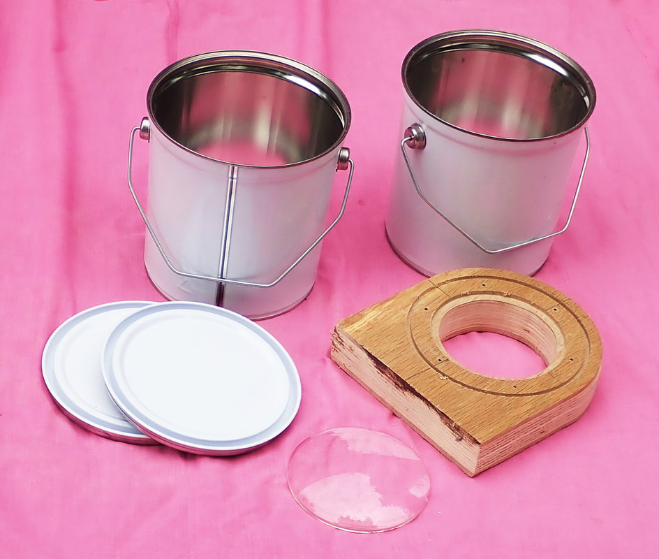
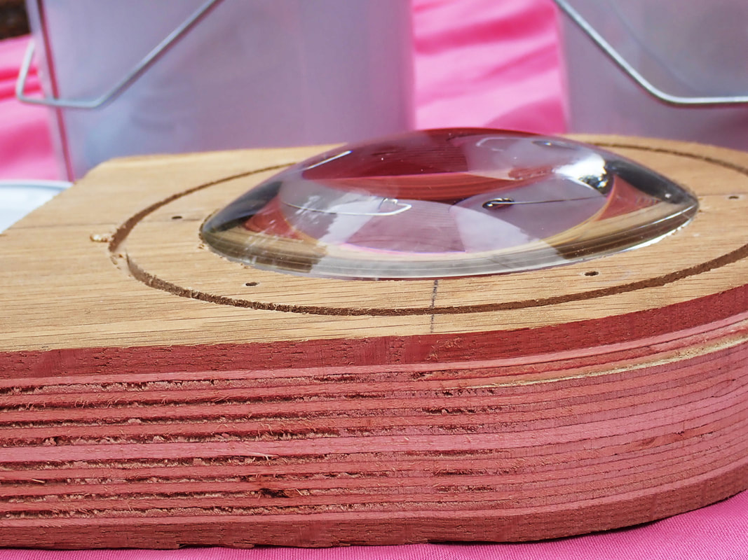
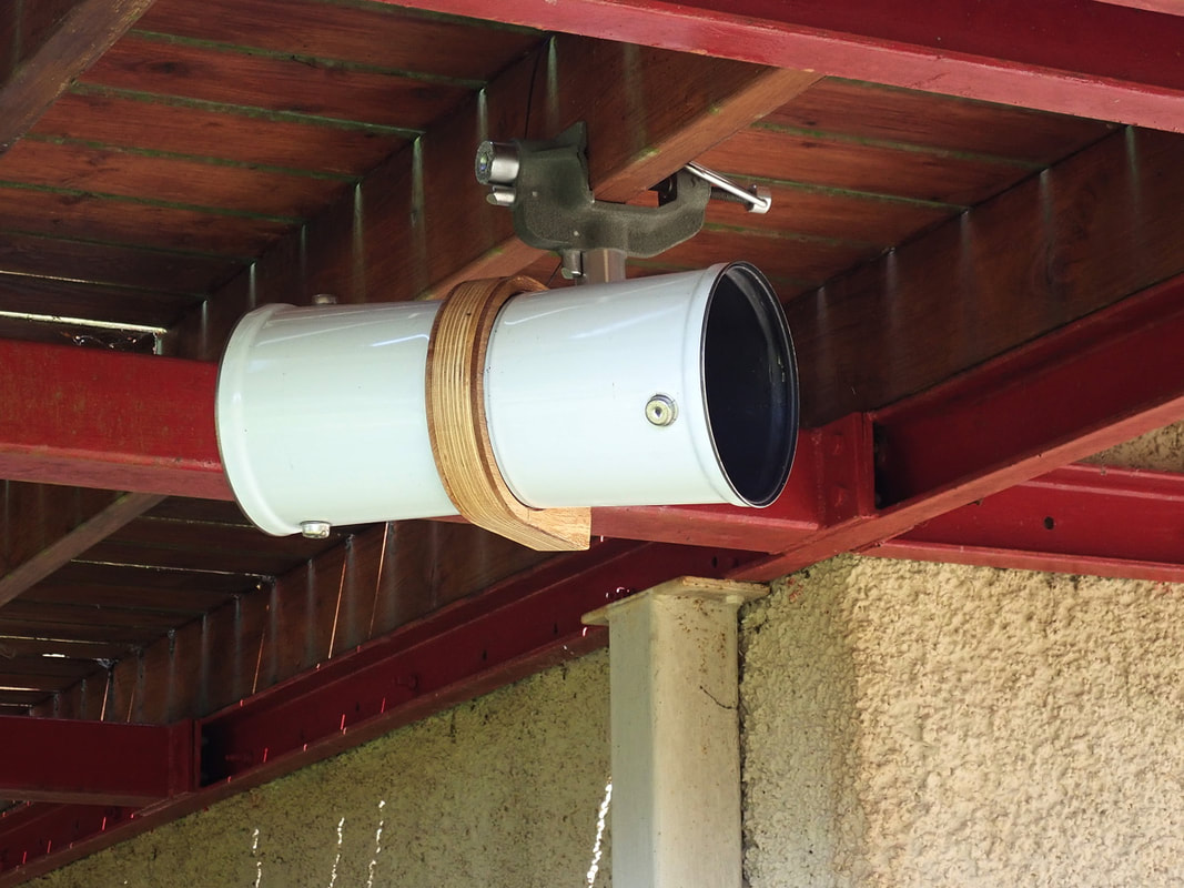
For the background to this story you will need to look back to my posts in July and October 2017. Not giving up despite the setbacks of last year, I can now report progress. The new camera needs at least to defeat the problems of 2017. One constraint remains – spinach is still the preferred light-sensitive material, and its sensitivity is very low. The f/2 lens is not really fast enough, but nothing faster is in sight, so we are committed to one exposure taking the whole summer. There is also no large budget for this experiment.
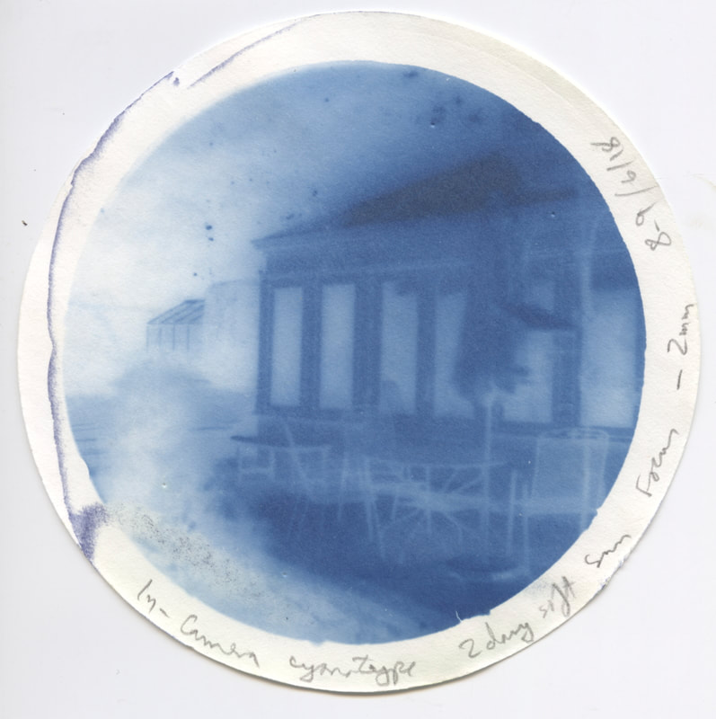
We have belt and braces to keep the paper dry and fungus-free – the sealed can, a bag of Molecular Sieve 3a (a desiccant) lying inside the camera, and a pinch of thymol fungicide mixed into the spinach juice coating the paper. However, before the 3-month trial using anthotype, it seemed prudent to run a 2-day exposure with cyanotype paper. I’d tried this in the first camera, and knew that would be the right exposure. Remember that the lens is a totally uncorrected single plano-convex lens intended as half of a condenser.
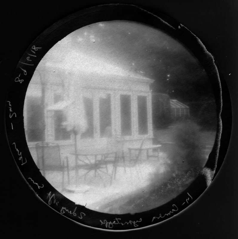
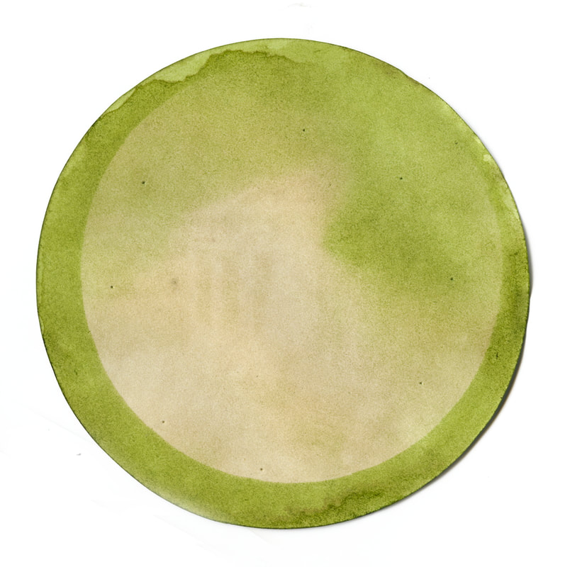
The test was successful, so on to anthotype. The paper is smooth drawing paper, double-coated with spinach; the juice made with a hand-held blitzer and filtered off with a coffee filter, a pinch of thymol crystals added. No ethanol but a little water was added. The aim was to prevent mould by a combination of a sealed environment, thymol and desiccant. That was a complete success, and when removed after three months the paper was dry to the touch and free from mould or fungus - unlike in 2017. The camera was pointed at the same scene as the cyanotype exposure, so we are looking for the same image as that. You can distinguish the main structure of the building – it looks better if you stand back and try for an overall impression – but much lower contrast and nowhere near the amount of detail to be seen in the cyanotype.
So was this a successful experiment? I would say definitely yes! As far as I know this is the first published in-camera anthotype. I confidently expect there to be very few others, this is not likely to be a new trending practice in photography. With exposure times of three summer months barely adequate to produce an image, only a few subjects are even possible, and the prospects of a body of work are near zero. However, a result was achieved against significant odds.
It is also worth noting that the test method, using cyanotype paper in-camera, is also hardly ever done but is a lot more promising as a practical technique. With exposures in single figures of days, you could certainly contemplate a series of images, of a rather magical nature. As for me, though, I shall declare success and move on. Continuing to use Kodak Aerographic 2645, as I have been doing some comparative testing of twin-lens reflexes that use 127 film (yes, I know, why would you?) In due course I hope to have a comparative report here so you can decide which to buy. Meanwhile a note on developing. As well as the late Patrick Gainer's ascorbate developer, I am trying his PC-TEA formula. You can read all about it here. P=phenidone, C=Vitamin C, TEA=triethanolamine. Thus PC-TEA. Now triethanolamine is an interesting liquid, because it is both an organic solvent and an alkali. That is to say, if you dissolve your developing agents (ascorbic acid=Vit-C and a pinch of Phenidone) in neat TEA (not tea!), they are not exposed to any water. The theory is that rather like rusting iron, for the developer to go off it needs to be in the presence of both air and water. So a stock solution of developing agents in TEA should have a very long shelf life. When you want to use it, 8ml of stock solution + 392ml of water makes 400ml of working developer, used 1-shot. The clever bit is that the TEA, having so far worked as the solvent, now becomes the alkali and activates the developers. The benefits are several - a very dilute working solution, so minimal environmental or health risks, long shelf life, cheap to make and use. And the actual performance is fine, with developing times similar to other brews. Vitamin C is safe to handle, TEA is a common ingredient of cosmetics (though it should not actually be drunk), and the phenidone content of the working solution is only 50 milligrams per litre. If there is a snag, it is that TEA is viscous at room temperature, so I find it best, when I make up a batch, to dose it into little screw-top tubes each containing 8ml (enough for 1 tank of working developer). While it is still hot, once you have dissolved the developing agents, it is easy to measure it into the tubes with a 10ml syringe. Here is a picture taken on Aerographic 2645, developed in PC-TEA. Camera - Yashica 44LM  Update some months later:
Storage life is looking good so far. The PC-TEA concentrate is pale straw colour when first made. After about 5 months, in little individual sealed glass tubes (10ml tubes containing 8ml of concentrate), the liquid has darkened to near-black, but still works as normal! |
ReflectedAn occasional and irregular blog, mostly of photographic experimentation and photographic history. Archives
June 2023
|
||||||||||||||||||||||||||||||||||||||||

 RSS Feed